
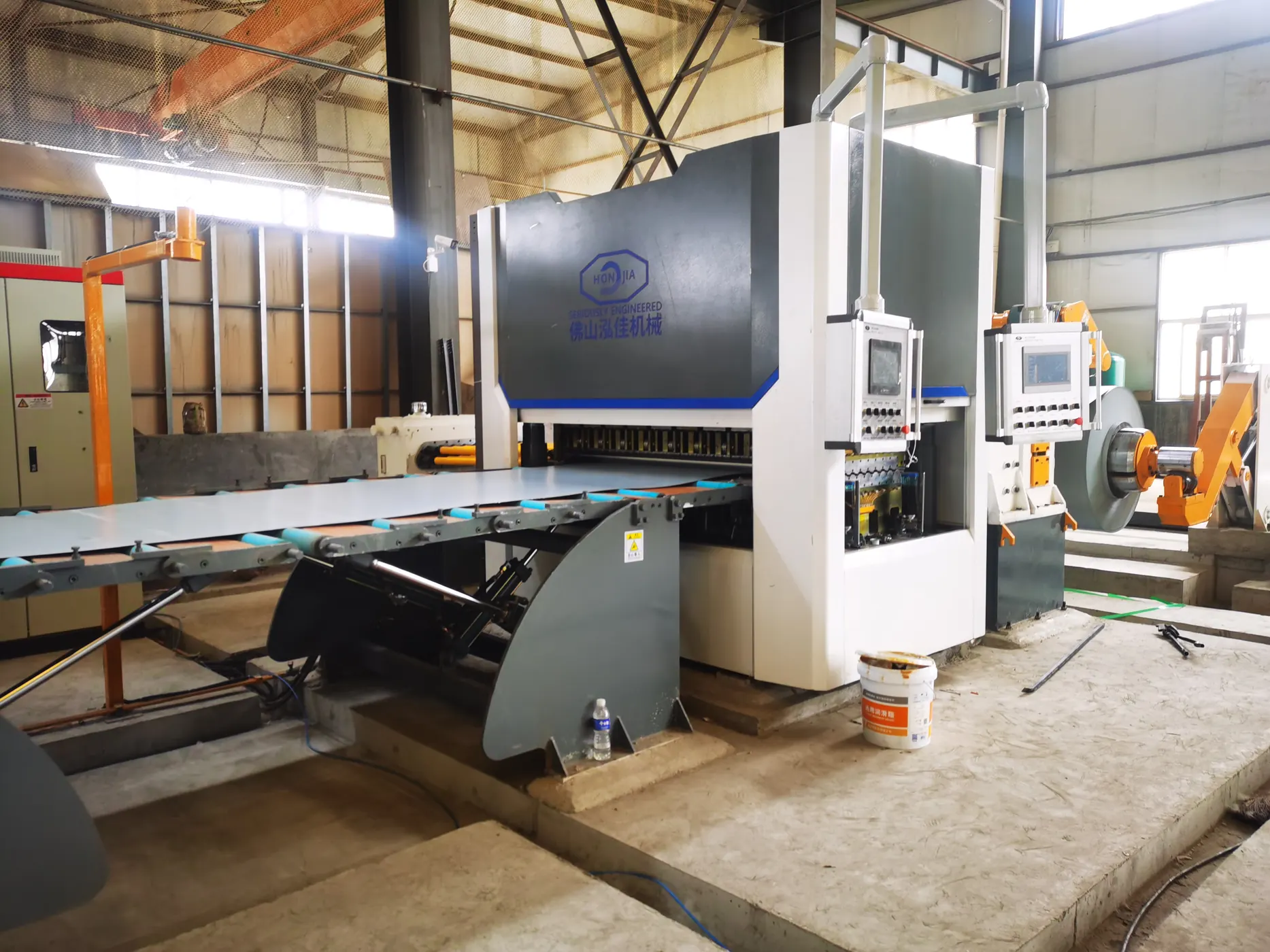
Use a gauge chart together with the material and the table’s source. A gauge number by itself is not a complete thickness specification. For an equipment inquiry, give the material grade and decimal thickness in millimeters or inches, plus the permitted material thickness range.
The table below reproduces selected decimal-inch thickness values from McNICHOLS’ Designer Metals reference, with calculated millimeter equivalents. It is a sheet-material reference, not a MAXDO machine capacity table or a material acceptance standard.
Using this reference
- Select the material column as well as the gauge number.
- Each cell gives inches / millimeters; millimeters are rounded to three decimal places.
- Check your material supplier’s convention and order specification before using a gauge value for procurement.
Gauge 26 to 10: sheet thickness reference
| Gauge | Carbon steel (in / mm) | Galvanized steel (in / mm) | Stainless steel (in / mm) | Aluminum (in / mm) |
|---|---|---|---|---|
| 26 | 0.0179 / 0.455 | 0.0217 / 0.551 | 0.0187 / 0.475 | 0.0160 / 0.406 |
| 25 | 0.0209 / 0.531 | 0.0247 / 0.627 | 0.0219 / 0.556 | 0.0180 / 0.457 |
| 24 | 0.0239 / 0.607 | 0.0276 / 0.701 | 0.0250 / 0.635 | 0.0200 / 0.508 |
| 23 | 0.0269 / 0.683 | 0.0306 / 0.777 | 0.0281 / 0.714 | 0.0220 / 0.559 |
| 22 | 0.0299 / 0.759 | 0.0336 / 0.853 | 0.0312 / 0.792 | 0.0250 / 0.635 |
| 21 | 0.0329 / 0.836 | 0.0366 / 0.930 | 0.0344 / 0.874 | 0.0280 / 0.711 |
| 20 | 0.0359 / 0.912 | 0.0396 / 1.006 | 0.0375 / 0.953 | 0.0320 / 0.813 |
| 19 | 0.0418 / 1.062 | 0.0456 / 1.158 | 0.0437 / 1.110 | 0.0360 / 0.914 |
| 18 | 0.0478 / 1.214 | 0.0516 / 1.311 | 0.0500 / 1.270 | 0.0400 / 1.016 |
| 17 | 0.0538 / 1.367 | 0.0575 / 1.461 | 0.0562 / 1.427 | 0.0450 / 1.143 |
| 16 | 0.0598 / 1.519 | 0.0635 / 1.613 | 0.0625 / 1.588 | 0.0500 / 1.270 |
| 15 | 0.0673 / 1.709 | 0.0710 / 1.803 | 0.0703 / 1.786 | 0.0560 / 1.422 |
| 14 | 0.0747 / 1.897 | 0.0785 / 1.994 | 0.0781 / 1.984 | 0.0630 / 1.600 |
| 13 | 0.0897 / 2.278 | 0.0934 / 2.372 | 0.0937 / 2.380 | 0.0710 / 1.803 |
| 12 | 0.1046 / 2.657 | 0.1084 / 2.753 | 0.1094 / 2.779 | 0.0800 / 2.032 |
| 11 | 0.1196 / 3.038 | 0.1233 / 3.132 | 0.1250 / 3.175 | 0.0900 / 2.286 |
| 10 | 0.1345 / 3.416 | 0.1382 / 3.510 | 0.1406 / 3.571 | 0.1000 / 2.540 |
Source: McNICHOLS, Designer Metals: Gauges, Thicknesses & Weights, selected sheet rows, accessed November 18, 2026. Its steel columns are labelled USS Gauge and its aluminum column B & S Gauge. The values here follow that supplier table consistently; the labels are not a statement that all suppliers use identical values.
Download the gauge reference with inch/mm values and source notes (CSV).
Why the material and source matter
At gauge 16, the selected reference gives carbon steel as 0.0598 in, stainless steel as 0.0625 in and aluminum as 0.0500 in. These are different thicknesses even though the gauge number is the same. Select the column before converting units.
Supplier references can also differ. For gauge 16 aluminum, Ideal Products’ published chart lists 0.0508 in, while the McNICHOLS source used above lists 0.0500 in. This page retains the McNICHOLS value and identifies the difference rather than silently substituting a value from another chart. For an actual order, ask the material supplier which reference and decimal thickness apply.
A difference between chart entries is not an allowed material tolerance. The order’s specified thickness, applicable material specification and agreed tolerance determine acceptance. The table does not establish any of those limits for a particular delivery.
Convert decimal inches and millimeters
NIST defines the international inch as exactly 25.4 mm. Multiply decimal inches by 25.4 to obtain millimeters; divide millimeters by 25.4 to obtain decimal inches.
For example, the chart’s gauge 16 carbon-steel entry converts as follows:
- 0.0598 in × 25.4 = 1.51892 mm.
- Displayed to three decimal places: 1.519 mm.
The inch-to-millimeter factor is exact. The precision of a source thickness entry and the rounded display are separate matters. Retain the original order value when checking a drawing or purchasing material, and do not treat a rounded chart value as a measured result.
Do not use interpolation to assign a gauge to a measured thickness that falls between rows. Report the measured thickness and the material specification instead of selecting a convenient gauge number.
Sheet gauge, tube wall thickness and material range
This chart covers the selected sheet reference only. It does not convert pipe schedules, wire gauges or an unidentified tube-wall gauge convention. For tube production or polishing, provide the wall thickness in decimal units and identify the drawing or material specification used.
Compare an equipment proposal with the actual minimum and maximum thicknesses required for the material and jobs. A chart value alone does not establish that a machine can process the grade, width, surface or output requirement. The published tube mill table and polishing tables use their own listed ranges; coil equipment requires a proposal for the stated job.
Put decimal thickness in the equipment request
A useful request identifies the grade, nominal thickness, permitted incoming variation, coil width and weight, and required output. For example: “Please assess coil slitting for the grade shown on the attached material specification. Our order states 0.0598 in nominal thickness; the supplier will confirm the permitted range. The required strip pattern and coil dimensions are recorded separately.” This is a wording example, not a confirmed job or equipment recommendation.
For narrower strip, use the slitting requirements sheet. For cut sheets, use the cut-to-length requirements and configuration table. Keep the material reference with those records so the equipment proposal is assessed against an identified thickness requirement.