
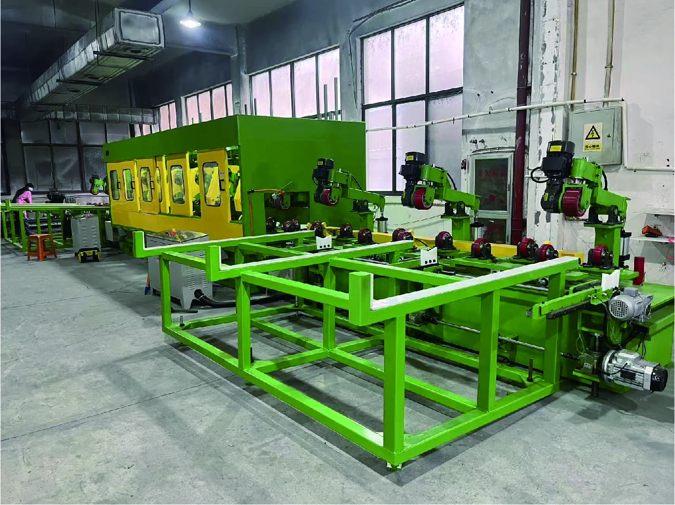
A factory layout review starts with the machine footprint, but it cannot stop there. Tube and pipe equipment also needs a clear material path, support points, operator access, inspection access and maintenance space. The current MAXDO catalog provides useful listed dimensions for several families, while final foundation, utility and safety-clearance requirements remain specific to the selected model and project.
Use this guide to prepare the information needed before a detailed installation discussion.
Material path from infeed to outfeed
Mark the complete path from input material to finished product:
- Material loading or strip entry.
- Machine infeed and support points.
- Processing area.
- Operator and control position.
- Inspection or transfer point.
- Finished-product removal and storage.
- Maintenance and cleaning access.
A machine can fit inside a rectangle and still fail the layout when the material cannot be loaded, supported or removed without crossing another process.
Listed machine footprint
The current records provide these useful comparisons:
| Family or model | Listed dimensions | Nominal rectangle calculation |
|---|---|---|
| MD-40S tube mill | 20 m × 1.0 m | 20.00 m² |
| MD-100 tube mill | 36 m × 3.5 m | 126.00 m² |
| MA-8 round-tube polishing | 7200 × 1300 × 1600 mm | 9.36 m² floor rectangle |
| MG-51 industrial pipe polishing | 10500 × 2200 × 1600 mm | 23.10 m² floor rectangle |
| Second-generation MD76 internal polishing | 13500 × 4500 × 2000 mm | 60.75 m² floor rectangle |
The calculations use only length × width. They do not include access, clearances, auxiliary equipment, utilities, foundations, storage or the full material path. Use them to compare scale and to identify layout questions, not as a final installation plan.
Operator, maintenance, inspection and material access
A first marked-up plan should show four separate zones:
| Zone | What to mark |
|---|---|
| Infeed | Where strip, tube or pipe enters and how it is supported |
| Operator | Control position, normal operating position and inspection point |
| Maintenance | Access to belts, polishing heads, drives, rollers and cleaning points |
| Outfeed | Finished tube or pipe removal, transfer and storage direction |
The exact dimensions of these zones are not published as a universal MAXDO standard. Keep them visible in the plan so the selected model can be reviewed against the actual factory.
Tube mill, outside polishing and inside polishing layouts
Tube mills, outside polishing and inside polishing do not use the same material path. A tube mill handles strip and produces welded tube. An external polisher guides an existing tube or pipe through the outside-surface process. An internal polisher must support the pipe while the tool reaches the inside wall.
If one project needs more than one process, draw each machine and the transfer between them. Do not combine the listed footprint rectangles and call the result a confirmed production line unless the project configuration has been defined.
Layout review information
Send the following information with the candidate model:
- a scaled floor plan or a dimensioned sketch;
- building length, width and usable height;
- columns, doors, walls and fixed machines;
- input and finished-product directions;
- material length, weight and support method;
- operator and inspection positions;
- maintenance and cleaning access;
- available electrical, air, cooling, dust-control and foundation information when known.
The current public records do not provide a complete universal utility or foundation schedule. That information should be reviewed against the selected model and confirmed project arrangement.
30 m × 5 m layout example
Suppose a factory has a clear 30 m × 5 m area and is considering MD-60 at a listed 26 m × 1.4 m:
- Available floor rectangle: 30 × 5 = 150 m².
- Listed machine rectangle: 26 × 1.4 = 36.4 m².
- Remaining rectangular area by arithmetic: 150 − 36.4 = 113.6 m².
The remaining area is not automatically usable clearance. The material path, operator position, maintenance access, fixed structures and confirmed auxiliary equipment still decide whether the layout works. The calculation is useful because it exposes the difference between machine footprint and actual installation planning.
Build the layout from the material path
Prepare a tube and pipe equipment layout from the full material path. Start with the listed machine dimensions, calculate the nominal footprint, then mark infeed, operator, maintenance, inspection and outfeed zones. Treat foundation, utilities and safety clearances as model-specific review items. This produces a useful first layout without turning a catalog rectangle into an unsupported installation promise.