Custom Light Gauge Coil Slitting Machines: Design & Manufacturing Guide
Expert guide to custom light gauge coil slitting machine design, engineering specifications, and manufacturing. Learn customization options for 0.3-3mm materials with precision tolerances.
When standard equipment falls short of your production requirements, custom light gauge coil slitting machines offer the precision, flexibility, and performance needed to maintain competitive advantage in metal processing operations. Unlike off-the-shelf solutions that force manufacturers to adapt their processes to equipment limitations, custom-engineered slitting systems align machine capabilities with specific material requirements, production volumes, and quality standards.
For production managers evaluating equipment investments, understanding the custom design and manufacturing process proves essential. A custom light gauge coil slitting machine delivers measurable advantages: 5-8% improvement in material yield, 40-60% reduction in setup time, and processing capabilities tailored to materials ranging from 0.3mm aluminum sheets to 3.0mm high-strength steel coils. This comprehensive guide examines the engineering specifications, customization options, and manufacturing considerations that transform standard slitting technology into optimized production assets. Whether processing pre-painted architectural panels or precision-grade electrical components, the right custom configuration ensures consistent quality while maximizing throughput and minimizing waste across diverse applications.
Understanding Custom Light Gauge Slitting Requirements
Light gauge slitting machines process materials between 0.3mm and 3.0mm thickness, requiring specialized tension control and surface protection that standard heavy-duty lines cannot provide. The fundamental challenge in light gauge processing centers on maintaining dimensional accuracy and surface integrity while managing materials that exhibit high sensitivity to tension variations, knife clearance settings, and handling contact.
Material-specific processing demands drive custom configuration requirements. Aluminum alloys require different knife geometries and clearance settings than galvanized steel. Pre-painted coils demand rubberized contact surfaces and controlled tension zones to preserve coating integrity. Each material category presents distinct engineering challenges that generic equipment cannot adequately address.
Custom configurations accommodate specific material types including aluminum alloys (1100, 3003, 5052), galvanized steel sheets, pre-painted coils with polyester or PVDF finishes, stainless steel grades (304, 316, 430), and specialty coated materials. The processing parameters for each material type differ substantially in optimal knife clearance (0.05mm to 0.15mm), line speed capability (80-300 m/min), and tension control requirements (5-50 kg per strip).
Application-driven customization addresses the distinct needs of automotive component manufacturers requiring tight width tolerances for door panels and structural reinforcements, architectural metal processors demanding scratch-free surfaces on building façade materials, HVAC fabricators processing ductwork materials with consistent edge quality, appliance manufacturers converting wide master coils into multiple narrow strips for cabinet panels, and electrical component producers requiring burr-free edges for transformer laminations.
Key differentiation from medium and heavy gauge lines includes reduced knife clearance adjustment ranges optimized for thin materials, enhanced tension zones with multiple servo-controlled braking points to prevent material stretching, coating preservation systems incorporating non-marring guides and controlled contact pressures, and higher-resolution width adjustment mechanisms enabling precise positioning for narrow slit widths. These specialized capabilities represent the foundation of effective light gauge processing but require custom engineering to match specific operational requirements.
Critical Design Parameters for Custom Systems
Coil width capacity customization forms the primary specification decision in custom light gauge slitting machine design. Standard configurations process coils from 300mm to 1650mm width, but custom systems accommodate intermediate widths that align with specific material suppliers and end-product requirements. The slitter head station configuration determines the maximum number of simultaneous strips, typically ranging from 6-30 strips depending on minimum slit width requirements and arbor design.
Manufacturers processing 1200mm-wide aluminum coils for architectural applications benefit from custom 1300mm capacity systems that eliminate material waste and allow optimal master coil purchasing. Similarly, operations focused on narrow-width electrical components may specify compact 600mm systems that reduce equipment footprint and capital investment while maintaining full processing capability for their material range.
Speed optimization based on material properties directly impacts production efficiency and equipment design requirements. Standard applications operate at 80-120 m/min, providing reliable processing for most light gauge materials with conventional mechanical drives and tension control systems. High-volume operations processing materials at 250-300 m/min require upgraded servo motor systems, enhanced dynamic braking capabilities, and accelerated knife positioning mechanisms to maintain quality at elevated speeds.
The relationship between material thickness and optimal processing speed follows established engineering principles: materials under 1.0mm thickness process effectively at higher speeds with appropriate tension control, while materials approaching 3.0mm thickness require reduced speeds to prevent knife shock loading and maintain edge quality. Custom configurations match drive system capacity and control responsiveness to target speed ranges, avoiding over-specification that increases cost without operational benefit.
Precision tolerance engineering represents a critical value proposition for custom light gauge systems. Achieving ±0.05mm width accuracy for materials between 0.3-1.2mm thick demands precision knife positioning systems with closed-loop feedback, thermally stabilized frames that minimize dimensional drift during operation, and calibrated measurement systems for setup verification. Less than 3% edge burr—calculated as burr height relative to material thickness—requires optimized knife geometry and clearance settings validated through material trials.
The engineering specifications supporting these tolerance capabilities include ground and hardened slitter arbors with concentricity under 0.01mm, servo-driven knife positioning with 0.02mm repeatability, and automated clearance adjustment systems that maintain optimal settings across varying material hardness. Custom systems incorporate material-specific knife packages with geometry optimized for target alloys, eliminating the compromise inherent in universal tooling approaches.
Knife specification selection addresses blade diameter (typically 180mm-300mm for light gauge applications), material grade (HSS, carbide-tipped, or solid carbide depending on production volume and material abrasiveness), and arbor configurations (fixed-station or quick-change systems). Aluminum processing benefits from carbide-tipped blades with specialized edge geometry that maintains sharpness across extended runs. Pre-painted materials require polished blade surfaces that minimize coating disturbance during cutting.
Tension control zones utilizing multi-zone servo systems prevent stretching and surface damage in materials under 1.0mm thickness. Custom configurations incorporate 3-7 independent tension zones depending on line length and material sensitivity, with each zone maintaining programmed tension regardless of upstream or downstream variations. This distributed control approach proves essential for ultra-thin materials where tension variations as small as 2-3 kg can cause permanent deformation or coating damage.
Manufacturing Customization Options
Entry system configurations determine how material enters the slitting line and significantly impact operational efficiency. Motorized decoilers with hydraulic expansion accommodate standard coil inner diameters of 508mm, 610mm, and 762mm, with custom configurations available for non-standard ID sizes common in specific regional markets or material suppliers. Weight capacity specifications ranging from 10T to 35T match anticipated master coil sizes, with structural reinforcement and expanded base designs supporting heavier loads.
Advanced entry systems incorporate powered coil cars that automatically position coils for threading, reducing manual handling and enabling faster changeovers. Coil end detection sensors trigger automatic threading sequences in fully automated configurations, eliminating operator intervention during standard operation. Custom hydraulic expansion systems adapt to varying coil ID tolerances, ensuring secure coil retention across material suppliers with different winding specifications.
The material threading mechanism—either manual with operator-assisted positioning or fully automated with powered threading arms—represents a significant customization decision affecting both capital cost and operational efficiency. High-volume operations processing multiple coils per shift justify automated threading systems that reduce changeover time from 15-20 minutes to 5-7 minutes, while lower-volume operations may specify manual threading with guided rollers that reduce cost while maintaining acceptable changeover efficiency.
Slitter head customization encompasses interchangeable tooling systems with quick-change capabilities that enable rapid conversion between material types or slit patterns. Servo-driven positioning systems memorize 100-200 blade setups, allowing operators to recall previous configurations by entering a recipe number rather than manually measuring and positioning each knife. This capability proves particularly valuable for operations processing diverse orders with frequently changing slit patterns.
Custom slitter head configurations address the specific knife spacing requirements of target applications. Architectural metal processors requiring wide slits (200-500mm) for panel materials specify widely spaced arbor stations, while electrical component manufacturers processing narrow strips (25-80mm) require compact arbor spacing that maximizes the number of simultaneous cuts. The arbor diameter selection—ranging from 180mm to 300mm—balances knife change frequency, operational rigidity, and dimensional stability during processing.
Recoiler specifications include single or dual-arbor systems matched to production requirements and available floor space. Single-arbor systems provide compact configurations suitable for operations with sequential processing workflow, while dual-arbor systems enable continuous operation by allowing operators to remove finished coils from one arbor while the second arbor continues winding. Programmable tension control maintains consistent winding tightness across the coil build, preventing telescoping that causes handling difficulties and potential material damage.
Automatic separation disc adjustment eliminates manual disc positioning between slit strips, reducing setup time and ensuring consistent disc placement that prevents strip contact during winding. Custom recoiler systems accommodate varying slit width combinations, automatically adjusting disc positions based on programmed recipes. This automation capability reduces setup errors and enables operators to manage wider product ranges without extensive training.
Loop pit integration creates buffer storage of 10-15m material length, enabling continuous processing during coil changeovers and providing tension isolation between entry and exit sections. Pit-mounted loop systems conserve floor space but require facility modifications during installation, while overhead loop configurations install more readily in existing facilities but consume vertical clearance. Custom loop designs match available facility dimensions while providing adequate buffer capacity for target processing speeds and typical changeover durations.
Automation level selection ranges from basic manual threading systems with operator-controlled positioning to fully automated entry configurations with integrated PLC programming for recipe management. Quality monitoring sensors provide real-time feedback on width accuracy, edge condition, and tension control, enabling predictive maintenance and quality documentation. Custom automation packages balance operational efficiency requirements against budget constraints and operator skill levels, avoiding over-automation in applications where simpler systems prove adequate.
Engineering Process: From Specification to Delivery
Phase 1 – Requirements analysis establishes the technical foundation for custom light gauge coil slitting machine design. Material specifications including thickness range, width range, alloy grades, coating types, and tensile strength define the core processing requirements. Production volume targets expressed in coils per day, shifts per week, and annual tonnage inform equipment sizing and automation level decisions. Facility layout constraints including available floor space, ceiling height, power supply characteristics, and material flow patterns shape equipment configuration and installation approach.
Existing line integration needs require detailed evaluation of upstream material preparation equipment and downstream processing systems. A custom slitting line feeding material to a cut-to-length line requires synchronized speed control and compatible coil handling systems. Integration with stamping operations demands precise width tolerances and edge quality standards that influence knife selection and tension control specifications.
The requirements analysis phase typically involves facility visits by applications engineers who document current operations, identify bottlenecks, and recommend optimized configurations. This collaborative approach ensures custom systems address actual operational challenges rather than theoretical specifications that may not reflect real-world requirements.
Phase 2 – Technical design translates requirements into detailed engineering specifications. Mechanical engineering drawings define frame construction, component mounting locations, and structural load paths. Control system architecture specifies PLC hardware, I/O configurations, HMI interface design, and integration protocols for quality monitoring sensors. Power calculations determine motor sizing, electrical service requirements, and energy consumption projections.
Tolerance validation modeling predicts dimensional accuracy under varying operational conditions, identifying potential thermal expansion effects, structural deflection patterns, and vibration characteristics. Finite element analysis of critical structures ensures adequate rigidity for target precision levels. Custom configurations undergo more extensive design validation than standard equipment to ensure specified performance across the full operating envelope.
Design review cycles include customer input on operational features, maintenance accessibility, and interface preferences. This collaborative design refinement ensures the final configuration aligns with operational workflows and maintenance capabilities while meeting technical specifications.
Phase 3 – Component selection determines the specific manufacturers and models for critical equipment elements. Knife material grades balance initial cost against operational life and edge quality requirements. Operations processing abrasive materials or high-volume applications specify premium blade materials that provide extended service intervals, while lower-volume applications may select standard grades that reduce capital investment.
Bearing specifications address anticipated loads, operating speeds, and maintenance intervals. Precision roller bearings with class ABEC-7 tolerances support high-accuracy applications, while standard industrial bearings prove adequate for less demanding specifications. Motor sizing calculations account for acceleration requirements, continuous operating loads, and regenerative braking capabilities in high-speed configurations.
Hydraulic system design determines pump capacity, accumulator sizing, and valve specifications for expansion mandrels, tensioning systems, and auxiliary functions. Custom systems optimize hydraulic capacity to actual requirements rather than using oversized standard packages that increase energy consumption and maintenance costs.
Phase 4 – Manufacturing and assembly employs precision machining of slitter arbors ground to specified tolerances, frame fabrication using stress-relieved steel assemblies, and systematic alignment procedures that establish geometric accuracy. Quality control checkpoints verify dimensional conformance at each manufacturing stage, ensuring finished equipment meets design specifications.
Custom frame configurations may require specialized welding procedures, non-standard material grades, or reinforced structures to accommodate unique loading conditions or facility constraints. The manufacturing process incorporates these variations while maintaining quality standards equivalent to standard equipment production.
Component integration follows documented assembly procedures with verification steps confirming proper alignment, clearance settings, and functional operation. Electrical systems undergo systematic testing of control circuits, safety interlocks, and monitoring functions before mechanical commissioning begins.
Phase 5 – Testing protocol validates performance through material trial runs using actual production materials when possible, or representative samples that simulate operational conditions. Speed testing confirms processing rates across the specified range while monitoring vibration, noise, and temperature characteristics. Width accuracy verification employs calibrated measurement systems to document slit width conformance under varying operating conditions.
Edge quality assessment examines burr height, edge straightness, and surface condition across different materials and thicknesses. Custom systems require more extensive testing than standard equipment to validate performance of specialized features and confirm operation within specified parameters.
Factory acceptance testing allows customers to witness equipment operation and verify performance before shipment. This quality assurance step identifies any discrepancies requiring correction while equipment remains in the manufacturing facility where remediation proves most efficient.
Typical lead time for custom configurations spans 12-16 weeks from design approval to factory acceptance testing. Complex integrations incorporating specialized automation, non-standard materials, or extensive custom engineering may extend to 18-20 weeks. This timeline includes design finalization (2-3 weeks), component procurement (4-6 weeks), manufacturing and assembly (4-6 weeks), and testing (1-2 weeks). Expedited delivery programs can reduce lead times by 2-3 weeks through priority material procurement and parallel manufacturing activities, though at premium cost.
Material-Specific Customization Strategies
Aluminum processing demands specialized knife geometries with reduced cutting angles that minimize work hardening and edge distortion in soft alloys. Custom blade profiles incorporate polished cutting edges that reduce friction and heat generation during cutting. Reduced clearances of 0.05-0.08mm (compared to 0.10-0.15mm for steel) accommodate aluminum’s lower hardness while maintaining clean edge separation.
Anti-scratch roller coatings using polyurethane or specialized rubber compounds protect aluminum surfaces throughout the processing path. Standard steel rollers create surface marking on soft aluminum alloys, particularly pre-finished architectural materials requiring pristine surface condition. Custom tensioning systems reduce contact pressures to minimum levels adequate for strip control, avoiding the excessive clamping forces that mark aluminum surfaces.
Aluminum’s thermal characteristics require attention to blade temperature management, as heat buildup during cutting can cause material adherence to blade surfaces. Custom lubrication systems apply minimal cutting fluid or air blast cooling to knife edges, maintaining optimal cutting temperatures without contaminating material surfaces destined for painted or anodized finishes.
Pre-painted and coated materials present distinct handling requirements that justify specialized customization. Rubberized tension drums with durometer ratings selected for coating hardness provide secure grip without marking painted surfaces. Standard knurled or serrated drums used for bare steel damage coating finishes through excessive localized pressure.
Non-marring guides fabricated from engineered polymers or rubber-coated steel replace standard metal guides throughout the material path. Each contact point receives evaluation for coating damage potential, with custom guide designs eliminating sharp edges and minimizing contact pressure. Controlled unwinding systems ramp tension gradually during coil startup rather than applying step changes that can crack or flake coating materials.
Edge protection extends beyond cutting operations to include powered separator discs that prevent strip-to-strip contact during recoiling. Custom separator systems maintain minimum clearance between adjacent strips while accommodating coating thickness variations that affect overall strip dimensions. This attention to coating preservation throughout processing ensures material maintains finish quality from entry to finished coil.
High-strength steel with tensile strength exceeding 400 MPa requires enhanced knife arbor rigidity to resist deflection under elevated cutting forces. Custom arbor designs incorporate larger diameter shafts, reinforced bearing housings, and rigid frame mounting that prevent dimensional shifts during cutting. These structural enhancements maintain knife clearance settings despite increased mechanical loads.
Increased motor power overcomes the higher cutting forces associated with high-strength materials. Custom drive systems provide 20-30% additional capacity compared to standard configurations, ensuring adequate power reserves for acceleration and maintaining speed during demanding cuts. Adjustable clearance systems enable optimization for varying material grades, as high-strength alloys require different clearance settings than standard mild steel even at equivalent thickness.
Tool life management becomes more critical with high-strength materials that accelerate blade wear. Custom configurations may incorporate automated blade changing systems that reduce downtime during knife replacement, or integrated blade sharpening systems that restore cutting edges without removing blades from arbors. These productivity features prove economically justified in high-volume operations processing abrasive or hard materials.
Ultra-thin gauges under 0.5mm demand precision web guiding systems with optical edge sensors that detect strip position with 0.1mm resolution. Standard mechanical guides prove inadequate for delicate materials that buckle under contact pressure. Custom guiding systems employ air flotation or minimal-contact rollers that maintain material alignment without inducing stress.
Static elimination systems discharge accumulated electrical charges that cause thin materials to attract debris, distort during processing, or adhere to handling equipment. Custom ionization bars positioned at strategic locations neutralize static buildup, improving material tracking and surface cleanliness. This proves particularly important for materials destined for laminating or coating operations where surface contamination causes defects.
Specialized edge support systems prevent tearing at slit edges where ultra-thin materials exhibit minimal resistance to lateral forces. Custom slitter head designs incorporate support knives or guide fingers positioned immediately adjacent to cutting points, providing lateral constraint during edge separation. This mechanical support eliminates edge tears that compromise material quality and increase scrap rates in thin-gauge processing.
Integration with Existing Production Lines
Compatibility considerations extend beyond dimensional interfaces to include control system integration and operational synchronization. Matching line speeds with downstream cut-to-length or stamping equipment ensures material flows efficiently between processes without accumulation or tension variations. Custom slitting systems incorporate variable speed drives that accommodate speed fluctuations in downstream equipment, maintaining consistent material flow across integrated operations.
Buffer accumulation systems store material between processing stages, isolating equipment with different operating characteristics. A slitting line feeding an intermittent stamping press benefits from accumulator integration that provides continuous operation despite downstream cycling. Custom accumulator sizing matches typical press cycle times and anticipated material consumption patterns, ensuring adequate buffer capacity without excessive floor space consumption.
Production scheduling synchronization requires communication protocols that share operational status between equipment controllers. Custom integration packages enable the slitting line to receive production schedules from enterprise systems, automatically configure blade positions for upcoming orders, and report completion status for inventory management. This connectivity reduces manual intervention and enables lights-out operation in highly automated facilities.
Coil handling system integration streamlines material movement through automated loading cars, coil staging systems, and slit coil packaging machines. Automated loading cars transport master coils from storage to the decoiler mandrel, eliminating manual forklift operation and reducing setup time. Custom loading systems accommodate facility-specific material flow patterns and available floor space, creating efficient staging areas that support continuous production.
Coil staging systems organize master coils and finished slit coils, maintaining production sequence while enabling material tracking through the manufacturing process. Custom staging designs incorporate RFID tracking, barcode scanning, or other identification systems that link physical coils to production records. This automated tracking eliminates manual paperwork and provides real-time inventory visibility.
Slit coil packaging integration automatically wraps, straps, and labels finished coils, creating shipping-ready products without manual handling. Custom packaging systems match customer packaging requirements, applying specific wrapping materials, strapping patterns, and labeling formats. This end-to-end automation from master coil to finished product eliminates handling touchpoints that slow production and increase damage risk.
Control system connectivity enables Industry 4.0 capabilities through standardized communication protocols including OPC-UA, Modbus TCP, and Ethernet/IP. Custom integration packages provide production data logging that captures operational parameters, quality metrics, and equipment status for analysis and optimization. This data flows to enterprise systems for overall equipment effectiveness (OEE) calculation, predictive maintenance scheduling, and production reporting.
ERP system integration eliminates duplicate data entry by automatically creating production records, updating inventory levels, and generating quality documentation. Custom connectivity packages map equipment data to specific ERP fields, ensuring information compatibility across systems. This integration proves particularly valuable for ISO-certified operations requiring comprehensive quality documentation and traceability.
Remote monitoring capabilities enable equipment manufacturers to provide technical support and predictive maintenance services. Custom connectivity packages balance operational data visibility with cybersecurity requirements, implementing appropriate network segmentation and access controls. This remote access capability reduces service response time and enables proactive maintenance that prevents unplanned downtime.
Space optimization addresses facility constraints through compact configurations for retrofit installations. Custom frame designs minimize equipment length by integrating functions that standard configurations treat as separate elements. Vertical integration positions components in multiple planes rather than linear arrangements, reducing floor space consumption in facilities with adequate ceiling height.
Overhead vs. pit-mounted loop systems present distinct installation trade-offs. Pit-mounted systems conserve vertical space but require facility excavation and may complicate maintenance access. Overhead loop configurations install without floor modifications but consume ceiling clearance. Custom loop designs consider facility characteristics, selecting the configuration that optimizes available space while maintaining operational functionality.
Electrical specifications accommodate regional voltage and frequency requirements through custom motor specifications and control system configuration. Equipment destined for North American installations specifies 480V 60Hz electrical systems, while European installations require 400V 50Hz configurations. Custom electrical designs extend beyond voltage matching to include power factor correction, harmonic mitigation, and energy recovery systems that optimize power consumption.
Power consumption optimization reduces operational costs through servo motor selection, regenerative braking implementation, and efficient hydraulic system design. Custom energy management systems monitor real-time power usage and identify opportunities for consumption reduction. This attention to energy efficiency provides measurable operational savings throughout equipment life, particularly in regions with high electrical costs or sustainability reporting requirements.
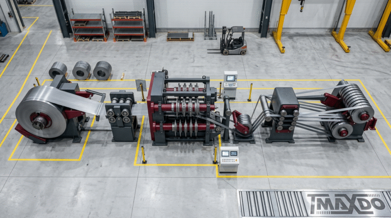
MaxDo MD Series Customization Capabilities
MD-850 custom configurations process materials from 300-820mm working width, with standard configuration optimized for 0.3-3.0mm light gauge applications. Extended-range configurations accommodate 4-12mm materials through upgraded slitter heads, reinforced frames, and increased drive power. This versatility enables a single equipment platform to serve diverse applications, reducing capital investment for operations processing varying material ranges.
Custom MD-850 systems incorporate material-specific optimization packages including aluminum tooling sets with specialized blade geometry and anti-scratch handling components, pre-painted material packages with non-marring guides and controlled tension systems, and high-strength steel packages with reinforced structures and enhanced drive capacity. These application-focused packages provide optimized performance without requiring extensive custom engineering, reducing cost and delivery time compared to fully custom designs.
Compact footprint configurations reduce floor space requirements in facilities with limited available area. These specialized layouts maintain full processing capability while consolidating components through vertical integration and function combination. The compact MD-850 configuration proves ideal for operations adding slitting capacity within existing production areas without facility expansion.
MD-1350 specialized options extend working width to 1350mm, addressing architectural and appliance applications requiring wider material processing. Custom configurations accommodate coil weights to 25-30T through reinforced decoiler structures and enhanced mandrel designs. This capacity range matches the largest master coils typically available in light gauge materials, eliminating width limitations in material sourcing.
Aluminum-optimized tooling packages provide complete solutions for architectural metal processors demanding scratch-free surfaces and precise tolerances. These packages include carbide-tipped blades with polished surfaces, polyurethane-coated tension drums, engineered polymer guides throughout the material path, and reduced-pressure tensioning systems. The integrated approach ensures consistent surface quality throughout processing, meeting stringent architectural material specifications.
High-speed configurations extend processing velocity to 280 m/min for high-volume operations. These specialized systems incorporate servo motor drives with rapid acceleration capabilities, dynamic braking systems that prevent overspeed during deceleration, and enhanced knife positioning mechanisms that maintain blade location accuracy despite increased dynamic forces. The performance improvement enables significant throughput increases without proportional floor space expansion.
MD-1650 high-volume systems deliver 300 m/min maximum speed capability for facilities requiring maximum throughput in light gauge processing. Custom configurations at this capacity level incorporate extensive automation including powered material threading, automated blade positioning recalled from recipe databases, and integrated quality control systems with real-time width measurement and defect detection.
The automated blade positioning system reduces changeover time from 20-30 minutes to 8-12 minutes by eliminating manual knife positioning. Operators enter order specifications through the HMI interface, and servo motors position each knife to programmed locations. Position verification sensors confirm proper placement before allowing operation to begin. This automation proves particularly valuable for facilities processing numerous small orders requiring frequent changeovers.
Integrated quality control incorporates laser micrometers that continuously monitor slit width during processing, automatically adjusting knife positions to maintain tolerances as blade wear progresses. Edge condition cameras detect burr formation or edge defects, alerting operators to quality issues before significant material waste occurs. These quality systems complement operator skill rather than replacing inspection, providing objective measurements that ensure consistent output.
ISO 9001 certified manufacturing ensures consistent build quality across custom specifications through documented procedures, systematic quality verification, and continuous improvement processes. Each custom configuration undergoes identical quality checkpoints as standard equipment, maintaining dimensional accuracy and functional performance regardless of customization extent. This quality assurance proves critical for custom systems where design variations could potentially compromise performance without systematic verification.
The certification process includes supplier qualification ensuring component quality, in-process inspection confirming conformance during manufacturing, and final testing validating performance before shipment. Custom configurations receive additional design review and prototype validation when incorporating significant engineering changes, ensuring reliability before full-scale manufacturing begins.
Post-installation support includes operator training programs customized to specific equipment configurations and operational requirements. Training covers standard operation procedures, changeover processes, routine maintenance tasks, and basic troubleshooting techniques. Custom training duration ranges from 2-5 days depending on automation complexity and operator experience levels.
Maintenance protocols provide scheduled service procedures that preserve equipment performance throughout operational life. Custom configurations may require specialized maintenance procedures for unique components or design features. Comprehensive maintenance documentation includes component specifications, adjustment procedures, and troubleshooting guides specific to the installed configuration.
Spare parts availability ensures rapid replacement of wear items and critical components. MaxDo maintains inventory of common wear items including slitter blades, separator discs, bearing assemblies, and hydraulic seals for standard configurations. Custom systems requiring non-standard components receive recommendations for spare parts inventory based on criticality and anticipated replacement frequency. This proactive approach minimizes downtime from parts unavailability.
Equipment life exceeding 10 years of continuous operation proves typical with proper maintenance. The robust construction and quality components justify this longevity, providing extended return on equipment investment. Upgrade paths enable aging equipment to incorporate newer control systems or automation features, extending useful life beyond original specifications while maintaining compatibility with evolving production requirements.
ROI Considerations for Custom Equipment
Material yield improvement represents the most significant operational benefit from custom precision engineering. Reducing scrap rates by 5-8% compared to standard equipment generates measurable cost savings, particularly for operations processing expensive materials like stainless steel or specialized alloys. The yield improvement stems from precise width control that minimizes trim allowances and optimized knife geometry that reduces edge defects requiring additional trimming.
A facility processing 10,000 tons annually at $2,000 per ton material cost realizes $100,000-$160,000 annual savings from 5-8% yield improvement. Over typical equipment life of 10+ years, these cumulative savings exceed the premium cost of custom configuration, providing substantial return on investment independent of other operational improvements.
Precise tolerance control enables tighter customer specifications that command premium pricing or open new market opportunities. The capability to consistently deliver ±0.05mm width tolerance allows bidding on applications requiring this precision, expanding addressable markets beyond standard tolerance capabilities. This revenue opportunity often justifies custom equipment investment even before considering cost reduction benefits.
Setup time reduction through automated blade positioning systems cuts changeover time by 40-60%, increasing effective production hours without extending shifts or adding equipment. A facility conducting three changeovers per day averaging 20 minutes each spends 60 minutes daily on non-productive setup activities. Reducing changeover time to 8-12 minutes through automation recovers 24-36 minutes daily—equivalent to 4-6% production capacity increase.
This capacity expansion enables serving additional customers, reducing lead times, or eliminating overtime operation. The financial impact varies by facility, but recovered capacity typically provides value equivalent to $50,000-$150,000 annually depending on material margin and production volume. These savings accumulate throughout equipment life while requiring minimal ongoing cost beyond normal maintenance.
Reduced changeover time enables economical processing of smaller order quantities, improving customer service and enabling market expansion into applications requiring frequent product changes. Standard equipment with lengthy changeover times forces minimum order quantities that may exclude smaller customers or specialty applications. Automated changeover capabilities transform these formerly unprofitable orders into viable business opportunities.
Energy efficiency through servo motor systems and regenerative drives reduces power consumption by 12-15% compared to conventional drive systems. A slitting line consuming 150kW average power operating 6,000 hours annually uses 900,000 kWh. Energy reduction of 12-15% saves 108,000-135,000 kWh annually. At $0.12/kWh industrial rate, this represents $13,000-$16,000 annual savings—significant over equipment life despite modest percentage reduction.
Regenerative braking systems capture energy during deceleration, returning power to the facility electrical system rather than dissipating it as heat through resistive braking. This technology proves particularly valuable in applications with frequent speed changes or intermittent operation. The energy recovery capability provides environmental benefits beyond cost savings, supporting corporate sustainability goals and reducing carbon footprint.
Servo motor efficiency extends beyond energy consumption to include reduced heat generation requiring less facility cooling, quieter operation improving workplace environment, and enhanced control responsiveness improving processing quality. These secondary benefits complement primary energy savings while improving operational conditions.
Typical ROI timeline of 18-24 months for high-volume operations reflects combined benefits from yield improvement, setup time reduction, and energy savings. Facilities processing 8,000-15,000 tons annually realize fastest payback through high material throughput that magnifies yield improvement benefits. Lower-volume operations extending to 30-36 months ROI still justify custom equipment investment based on quality capabilities enabling market access or premium pricing.
The calculation methodology considers equipment premium cost (typically 15-30% above standard configurations), annual operational savings from yield improvement, recovered capacity value, and energy cost reduction. Financial modeling should include facility-specific material costs, production volumes, and energy rates to develop accurate ROI projections. Conservative assumptions using lower range estimates provide confidence in projected returns even if optimistic scenarios prove unrealistic.
Total cost of ownership analysis** extends beyond initial investment to include maintenance costs, spare parts expenses, operational efficiency, and expected service life. Custom equipment designed for specific applications typically provides lower total ownership cost than generic equipment despite higher initial investment. The optimized design reduces unnecessary features while enhancing critical capabilities, resulting in efficient operation matched to actual requirements.
Maintenance cost considerations include accessibility of wear components, availability of replacement parts, and complexity of service procedures. Well-designed custom systems provide excellent maintenance access and utilize standard components where possible, avoiding the maintenance penalties sometimes associated with specialized equipment. This design philosophy balances customization benefits against ongoing operational requirements.
Long-term operational savings compound throughout equipment life, with cumulative benefits far exceeding initial investment premiums. A 10-year operational horizon magnifies ROI dramatically compared to short-term analysis, yet equipment service life typically extends 12-15 years with proper maintenance. This longevity provides extended return period that justifies custom configuration investment for facilities committed to specific material processing applications.
Заключение
Custom light gauge coil slitting machines deliver measurable operational advantages through precision engineering matched to specific material requirements, production volumes, and quality standards. The investment in custom configuration proves economically justified through improved material yield (5-8%), reduced setup time (40-60%), and enhanced energy efficiency (12-15%) that combine to provide ROI within 18-24 months for most high-volume operations.
Successful custom equipment specification requires systematic evaluation of material characteristics, production requirements, facility constraints, and integration needs. The engineering process from requirements analysis through factory testing ensures delivered equipment meets operational expectations while maintaining the quality standards expected from ISO 9001 certified manufacturing.
MaxDo’s MD Series provides proven custom slitting platforms with over 500 global installations validating design reliability and performance capabilities. Whether processing 0.3mm aluminum sheet for architectural applications or 3.0mm high-strength steel for automotive components, custom-configured MD systems deliver the precision, speed, and flexibility modern metal processing operations demand.
Contact MaxDo’s applications engineering team to discuss your specific custom light gauge coil slitting machine requirements and receive detailed technical proposals addressing your operational challenges.
ЧАСТО ЗАДАВАЕМЫЕ ВОПРОСЫ
What thickness range defines light gauge in custom slitting machines?
Light gauge typically ranges from 0.3mm to 3.0mm thickness, though some custom systems extend capabilities to 4mm for applications requiring flexibility across material ranges. The optimal thickness range depends on material type and tensile strength—softer materials like aluminum process effectively across the full range, while high-strength steel may require specialized configurations above 2.5mm thickness. Custom machine configuration considers actual production material mix rather than theoretical maximum capability, ensuring equipment optimization for materials comprising the majority of production volume.
How long does custom slitting machine design and manufacturing take?
Standard customization requires 12-16 weeks from specification approval to factory acceptance testing and shipment. This timeline includes design finalization (2-3 weeks), component procurement (4-6 weeks), manufacturing and assembly (4-6 weeks), and testing (1-2 weeks). Complex integrations incorporating specialized automation features, non-standard materials, or extensive custom engineering may extend to 18-20 weeks. Expedited delivery programs can reduce lead times by 2-3 weeks through priority component ordering and parallel manufacturing activities, though at premium cost. Planning for installation scheduling and operator training should consider 2-4 weeks additional time after equipment delivery.
Can custom light gauge slitters process multiple material types?
Yes, through interchangeable tooling packages and adjustable knife clearances. Custom systems accommodate aluminum, carbon steel, stainless steel, galvanized materials, and pre-painted coils using material-specific blade sets and handling configurations. Quick-change tooling systems enable conversion between material types in 30-60 minutes, making multi-material processing economically viable for facilities serving diverse markets. The control system stores processing parameters for different materials, allowing operators to recall appropriate settings rather than manually determining optimal configurations for each material change. Facilities processing substantially different materials—such as soft aluminum and high-strength steel—benefit most from custom configurations that accommodate the full material range rather than compromising performance with generic settings.
What accuracy can custom light gauge slitting machines achieve?
Premium custom systems deliver ±0.05mm width tolerance for materials 0.3-1.2mm thick and ±0.1mm for 1.2-3.0mm materials under optimal conditions. Edge burr under 3% of material thickness represents standard achievement for properly configured systems using appropriate blade geometry and clearance settings. Achieving these precision levels requires servo-driven knife positioning with closed-loop feedback, thermally stable frames minimizing dimensional drift, and systematic calibration procedures. Material characteristics influence achievable accuracy—soft, uniform materials like aluminum allow tighter tolerances than hard, variable materials. Custom systems optimize all factors affecting precision rather than relying solely on positioning accuracy, ensuring consistent performance across production conditions.
How does customization affect machine price and ROI?
Custom features typically add 15-30% to base equipment cost depending on the extent of modification from standard configurations. Minor customizations like specialized width capacity or upgraded drive systems add 15-20%, while extensive automation integration or unique material handling requirements may reach 25-30% premium. However, custom features improve material yield by 5-8% and reduce setup time by 40-60%, generating operational savings that offset higher initial investment. Most high-volume operations (8,000+ tons annually) achieve ROI within 18-24 months through combined yield improvement, capacity recovery, and energy savings. Lower-volume operations realize ROI in 30-36 months, still justifying investment based on capabilities enabling market access, premium pricing, or quality requirements unattainable with standard equipment.