Cut-to-Length Process Main Page: CTL Station Map
The main MaxDo cut-to-length process page for mapping CTL stations: coil loading, leveling, feed control, shearing, stacking, acceptance checks, RFQ data, and CTL product routes.
The cut-to-length process converts coil into flat sheets through a fixed sequence: coil loading, decoiling, leveling, feeding to length, shearing, transferring, stacking, and inspection. Each station has a different job. A useful CTL specification should define what enters the station, what the control system must hold, and what output the buyer will accept.
This page is the single main process page for the MaxDo cut-to-length process topic cluster. It is the trunk page for CTL station sequence, station-by-station acceptance, and the route from coil entry to stacked sheets. Support pages should handle narrower questions such as CTL definition/RFQ intake, upstream coil-processing workflow, CTL supplier comparison, gauge boundaries, servo feed positioning, and product-family routing.
For a short definition and RFQ intake page, use what is a cut-to-length line. For the upstream coil-processing route, use the sheet metal coil processing workflow map. For CTL supplier comparison, use the CTL supplier acceptance matrix. For equipment routing, use the metal cut-to-length line category.
Map the CTL Process by Station
| CTL station | Main control point | Acceptance output |
|---|---|---|
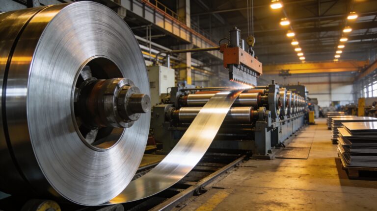
| Coil loading and decoiling | Coil centering, mandrel support, strip threading, payoff tension | Stable strip entry without edge damage or sudden tension spikes |
| Leveling | Roll penetration, backup support, material strength, coil set correction | Flat sheet stock within the agreed flatness target |
| Feed and measuring | Encoder or servo feed accuracy, slip control, acceleration, stop position | Repeatable sheet length and squareness before cutting |
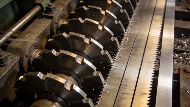
| Shearing | Blade gap, shear timing, cut angle, strip support, cycle rate | Clean cut edge, correct length, no unacceptable bow or marking |
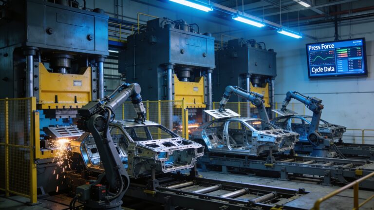
| Transfer and stacking | Conveyor timing, sheet support, magnetic or vacuum handling, stack alignment | Usable bundles with protected surfaces and predictable handling |
Start With Coil Entry Conditions
The process begins before the leveler. Incoming coil width, coil weight, ID/OD, grade, thickness, coating, and edge condition determine how the decoiler, coil car, peeler, pinch rolls, and guides should be sized. Poor coil centering or unstable payoff tension can create tracking problems that later stations cannot fully repair.
If the plant must decide whether to make slit coils or flat sheets, compare slitting vs CTL line production fit before finalizing the process route. For material-specific behavior across aluminum, stainless, and mild steel coils, review the slitting or CTL by material guide.
Treat Leveling as the Quality Gate
Leveling is the station that turns coiled strip into usable flat stock. The buyer should define the defect target in practical terms: coil set, crossbow, edge wave, center buckle, surface marking, or laser-table flatness. The supplier should explain leveler roll count, roll diameter, backup support, adjustment method, and how settings will change by thickness and material strength.
For light and medium gauge selection boundaries, use the light vs medium gauge CTL boundary matrix. If thickness language in the RFQ is unclear, use the gauge thickness RFQ helper to convert gauge into engineering inputs.
Define Feed Control and Shear Timing Together
Length tolerance is not only a feed specification. It also depends on strip slip, acceleration, deceleration, shear response, blade condition, and how the strip is supported during the cut. A CTL RFQ should state target sheet length range, tolerance, maximum short-sheet cycle rate, squareness requirement, and whether stop-start feeding or flying shear logic is required.
For the control logic behind feed positioning, use the servo roll feeder and grip feed positioning architecture. For the upper-level automation scope across coil lines, use the automated metal processing system map.
Specify Stacking as Part of the Process
Stacking is often treated as the end of the line, but it can decide whether the process is usable. Light sheets, stainless sheets, aluminum sheets, coated panels, and heavy blanks need different transfer and stacking logic. Define stack height, bundle weight, surface protection, sheet support, pallet method, and downstream handling before approving the line layout.
Build the CTL Process Acceptance Checklist
- Coil entry: coil width, weight, ID/OD, grade, thickness, coating, edge condition, and loading method.
- Leveling: flatness target, defect type, roll count, material range, setting method, and sample inspection.
- Feed and cut: sheet length range, tolerance, squareness, shear type, blade gap, and cycle-rate requirement.
- Stacking: transfer method, surface protection, bundle weight, pallet method, and downstream handling.
- Acceptance evidence: test coil, FAT/SAT checklist, measurement method, operator training, and deviation handling.
Connect the Process to CTL Equipment Paths
After the station requirements are clear, compare the metal cut-to-length line category, including CT-850, CT-1350, and CT-1650. If the same plant also needs slit strip output, compare the metal slitting machine category and the metal slitting line process guide.
To request a CTL process review, send MaxDo the coil data, material range, finished sheet length, flatness target, tolerance, surface requirement, stack requirement, expected volume, and acceptance test expectations through the contact form.