
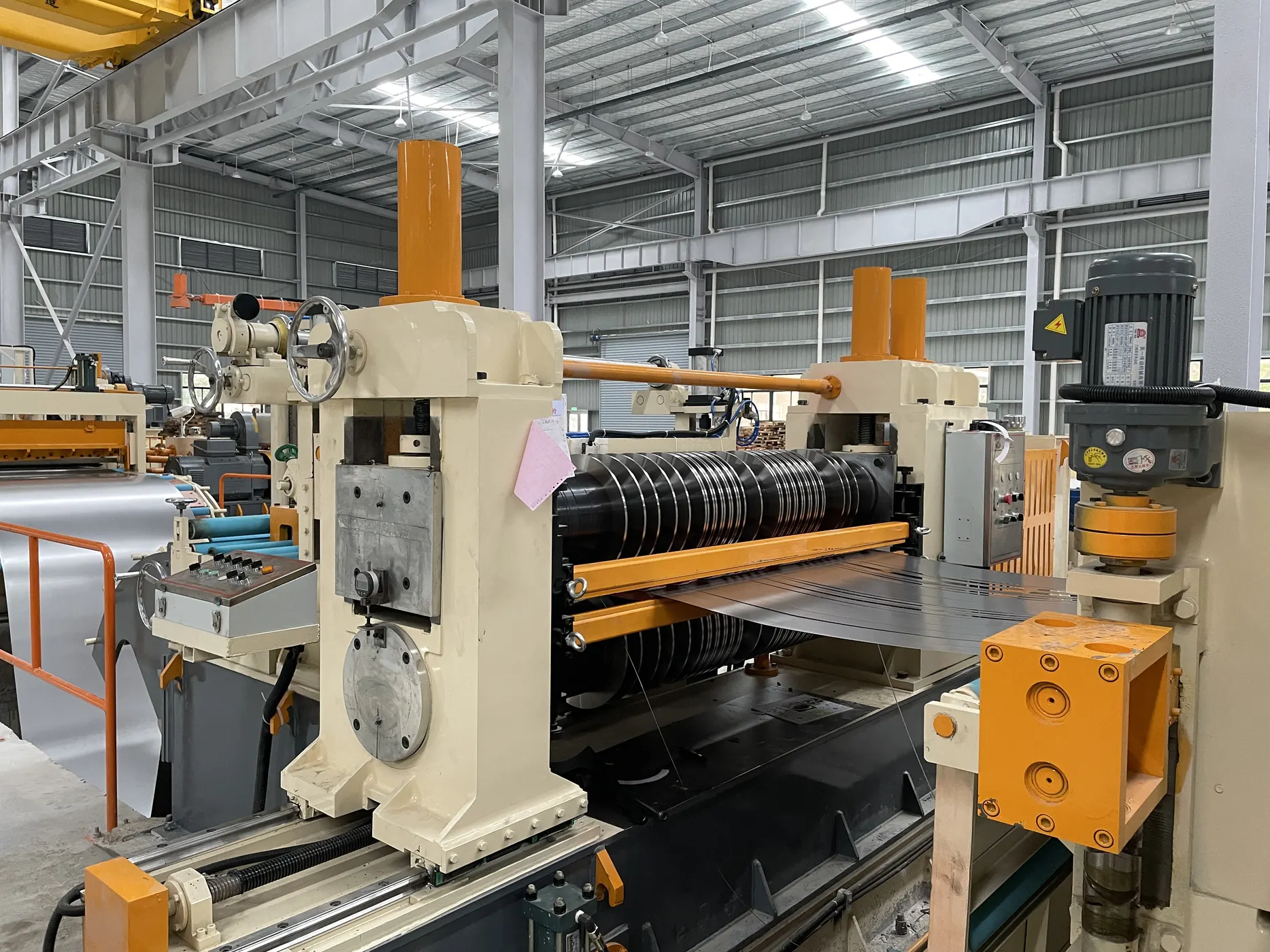
A slit strip can meet nominal width and still fail its next operation because of the edge, shape or surface condition. A useful quality specification therefore separates width tolerance from burr, edge damage, camber and surface marking. It also states how each item will be checked.
No single tolerance or knife setting applies to every metal grade, thickness and strip pattern. Obtain the proposed machine’s confirmed capability for the actual order rather than transferring a number from an unrelated application.
Define width and its measurement method
Write nominal width and permitted deviation for each slit position. Identify the instrument, sample location and inspection frequency agreed with the supplier. State whether measurements are made on a supported, released sample or in another defined condition.
Label samples by coil and strip position. Where readings vary along a strip, retain the sequence instead of reporting only the best or average reading. Agree how nonconforming samples are handled before production acceptance.
Treat edge condition as a separate requirement
Burr, damaged edges and visible edge irregularities require their own acceptance description. State any downstream sensitivity, such as a forming operation that depends on a consistent edge. Supply a representative acceptable sample or an agreed inspection method where words alone leave room for interpretation.
Do not use a width measurement as a substitute for edge inspection. Similarly, a visually clean edge does not establish that all slit positions satisfy the dimensional requirement.
| Quality field | What to agree | Useful record |
|---|---|---|
| Width | Nominal value, deviation and method | Readings by strip position and sample location |
| Burr and edge | Limit or reference sample and method | Edge photographs and inspection results |
| Shape | Camber or waviness requirement | Sample length and support condition |
| Surface | Allowed marking and protection | Photos with incoming and processed samples |
| Traceability | Coil, order and tooling identification | Linked setup and inspection sheet |
Collect evidence before changing the setup
If a problem appears, record whether it affects every slit position or only some positions. Note when it started and whether it followed a coil change, tooling change or maintenance event. Compare actual readings with the approved setup record.
The manufacturer’s instructions must govern tool condition, assembly and adjustment. Do not prescribe clearance, overlap, tension or tightening values from a generic article. A qualified setup review needs the material and equipment details as well as the defect sample.
Evaluate representative production jobs
For a new line, choose trial jobs that represent the material range, narrow strips and common width patterns. State the accepted edge and surface condition alongside the width requirement. Confirm whether the acceptance applies to every strip and how sampling will demonstrate it.
Discuss those records with the coil slitting equipment requirements. If the main issue is shape after cutting rather than width, use the deformation diagnostic checklist to describe the observation before proposing adjustments.
Technical reference
Braner USA: Slitting Lines discusses width consistency, edge quality, tracking and tooling as distinct line considerations. No numerical performance claim from that page is applied to MAXDO equipment.