Servo Feed Positioning Architecture Matrix
A narrow servo feed positioning architecture matrix for CTL and coil lines, covering feed loops, encoder feedback, slip control, cut timing, surface protection, and RFQ data.
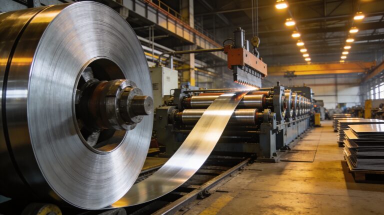
Servo roll feeder and grip feed systems control how coil material moves before cutting, forming, stacking, or recoiling. The key question is not only feed speed. The buyer must know how the line measures position, prevents slip, synchronizes with the shear or press, protects the surface, and records the data needed for repeatable production.
This page is a narrow support page for servo feed positioning architecture in the MaxDo topic network. It owns only the feed-control layer: position measurement, encoder feedback, slip prevention, shear or press synchronization, surface protection, and repeatable data records. It is not the main CTL process page, not a supplier acceptance matrix, and not a broad automation execution plan. For full CTL supplier acceptance, use the CTL supplier acceptance matrix. For overall automation execution, use the metal production line automation execution plan. This page focuses on the feed-control layer itself.
Define the Feed Control Problem
In a cut-to-length or press-feeding workflow, the feeder must advance material to a commanded position, stop or synchronize at the right moment, and release the material without adding marks or stretch. The architecture depends on material thickness, surface finish, yield strength, strip width, lubrication, line speed, cut length, tolerance target, and downstream process.
| Control layer | What it does | RFQ evidence to request |
|---|---|---|
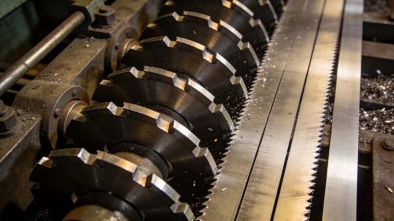
| Servo roll feed | Advances material with controlled roll rotation and feedback | Motor sizing, roll material, encoder feedback, acceleration profile |
| Grip or clamp feed | Holds material mechanically to reduce slip during indexed moves | Clamp force, surface protection, stroke repeatability, release timing |
| Loop control | Buffers speed differences between uncoiling, leveling, feeding, and cutting | Loop sensor type, alarm logic, speed synchronization method |
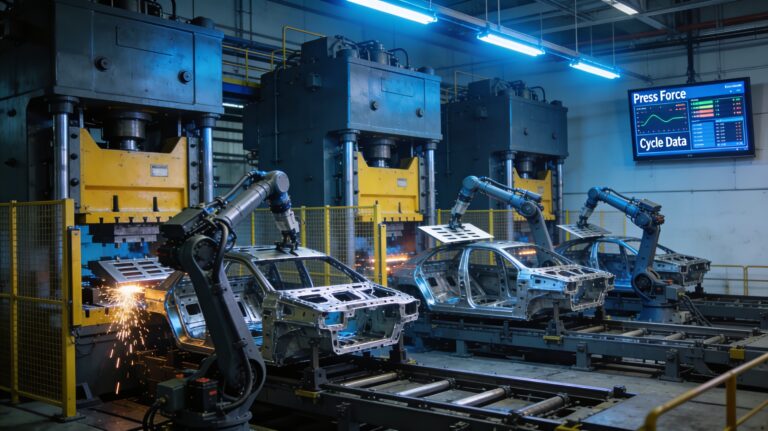
| Cut timing | Synchronizes feed length with shear, press, or blanking action | Trigger logic, tolerance measurement, test cut report |
Match Feed Method to Material State
Thin, coated, or surface-sensitive material may need non-marking rolls and careful tension control. Thick or high-strength material may need stronger clamping, slower acceleration, and more conservative feed profiles. For material intake before feed-system selection, use the MD series material compatibility checklist and the gauge thickness RFQ helper.
Connect Feed Control to CTL Quality
In CTL lines, feed control affects length tolerance, squareness, surface condition, stacking rhythm, and shear timing. A supplier should explain how the feeder works with the leveler, shear, conveyor, and stacker. For the full process sequence, use the cut-to-length process guide. For light and medium gauge CTL selection, compare the light vs medium gauge CTL guide.
Connect Feed Control to Automation Data
Servo and grip feed systems should generate useful operating signals: feed length, actual position, slip alarm, loop state, cut count, speed, fault history, and recipe data. These signals become more valuable when connected to line-level HMI and production data. For the data architecture layer, use the Industry 4.0 metal processing architecture guide. For retrofit planning, use the slitting line control system upgrade roadmap.
Servo Feed RFQ Checklist
- Material data: grade, thickness, strength, width, coating, lubrication, surface sensitivity, and coil condition.
- Feed target: length range, tolerance, acceleration, cycle rate, stop/start pattern, and downstream timing.
- Control method: servo roll, grip feed, combined feed, encoder type, loop control, and slip detection.
- Quality evidence: test cuts, length records, squareness checks, surface inspection, and alarm logs.
- Integration scope: HMI recipes, PLC interface, safety interlocks, remote diagnosis, and operator training.
Route Feed Requirements to Equipment Paths
For CTL equipment, compare the metal cut-to-length line category, including CT-850, CT-1350, and CT-1650. If the workflow also includes slitting, start from the sheet metal coil processing workflow map and the metal slitting machine category.
To request feed-system guidance, send MaxDo the material data, thickness range, feed length range, tolerance target, downstream machine, surface requirement, and automation interface through the contact form.