
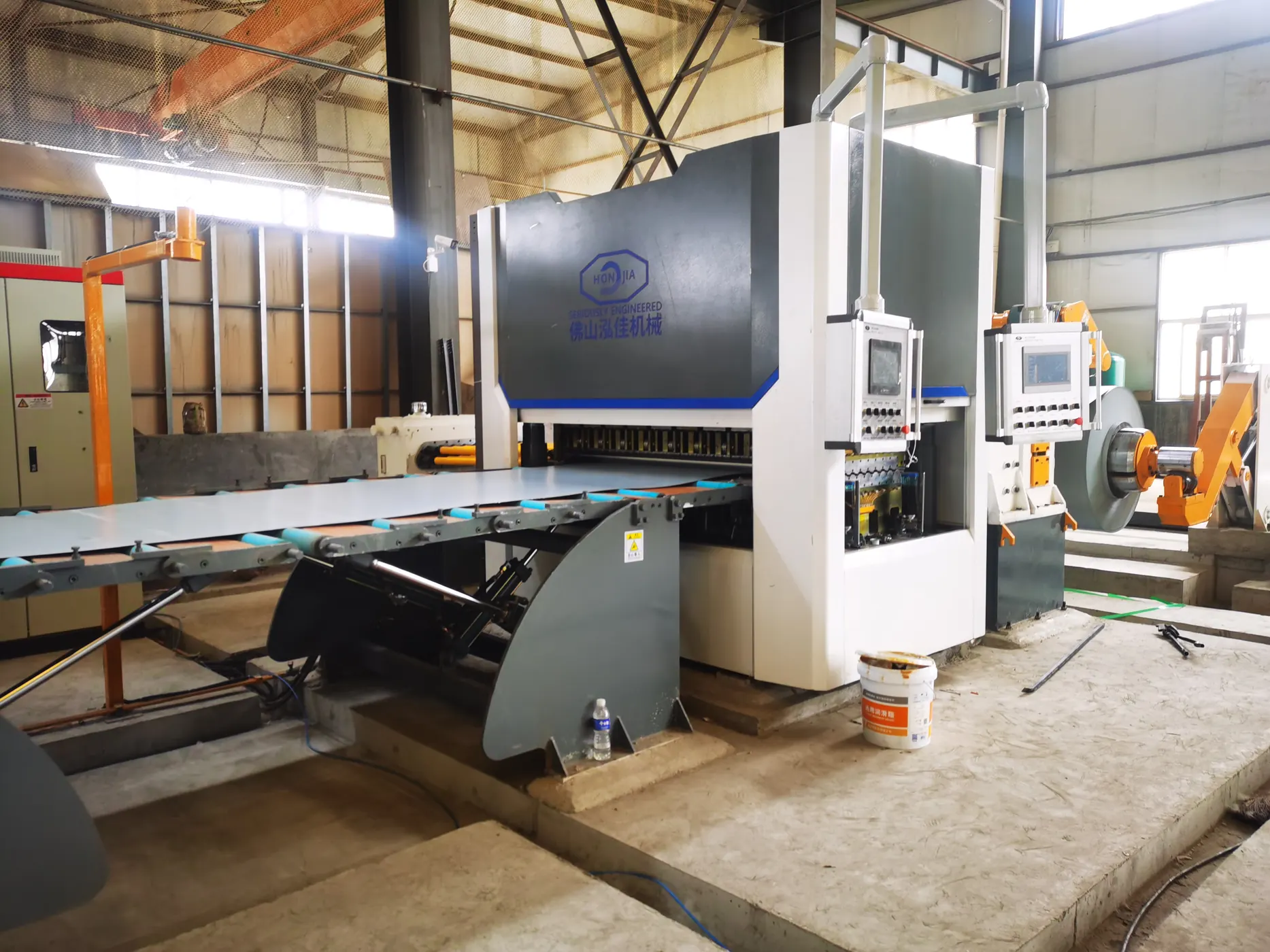
Cut-to-length (CTL) processing converts metal coil into sheets or plates of a specified length. A typical line unwinds the coil, controls its path, levels the material, measures the feed and cuts across the strip. Exit equipment transfers and stacks the finished sheets. The exact arrangement depends on the material and production requirement.
CTL is different from slitting: slitting divides the coil along its length to make narrower strips, commonly rewound into coils. CTL makes separate sheets. Neither process name alone defines the machine’s complete configuration.
Uncoiling and feeding
The entry section holds the coil and introduces the strip into the line. Coil weight, width, inside diameter and outside diameter determine the handling requirement. Material grade and thickness must be stated as well: coils with the same dimensions can require different processing forces.
Before ordering, identify how coils reach the machine, where loading takes place and how the leading end is handled. A drawing should show the loading area alongside the processing path, rather than only the machine footprint.
Leveling the strip
Leveling addresses material shape before the sheet is cut. Coil set, crossbow and waviness describe different shape conditions; a single statement such as “flat sheet” is not a complete acceptance requirement. Specify how flatness will be measured and what the downstream process needs.
A good cut length does not prove good flatness. Equally, sheet that looks flat on a table may behave differently after subsequent cutting. Include the planned downstream operation when discussing the leveling arrangement.
Measuring length and shearing
Length control coordinates material feed and the cross-cut. Some lines stop the feed for cutting; flying-shear arrangements cut while material continues moving. These are configuration choices, not features that should be assumed from the CTL label.
Keep requested running speed separate from accepted sheets per hour. Sheet length, cutting cycle, transfer and stacking can all affect finished output. Ask for a production assessment using the actual range of sheet sizes rather than comparing maximum speed figures alone.
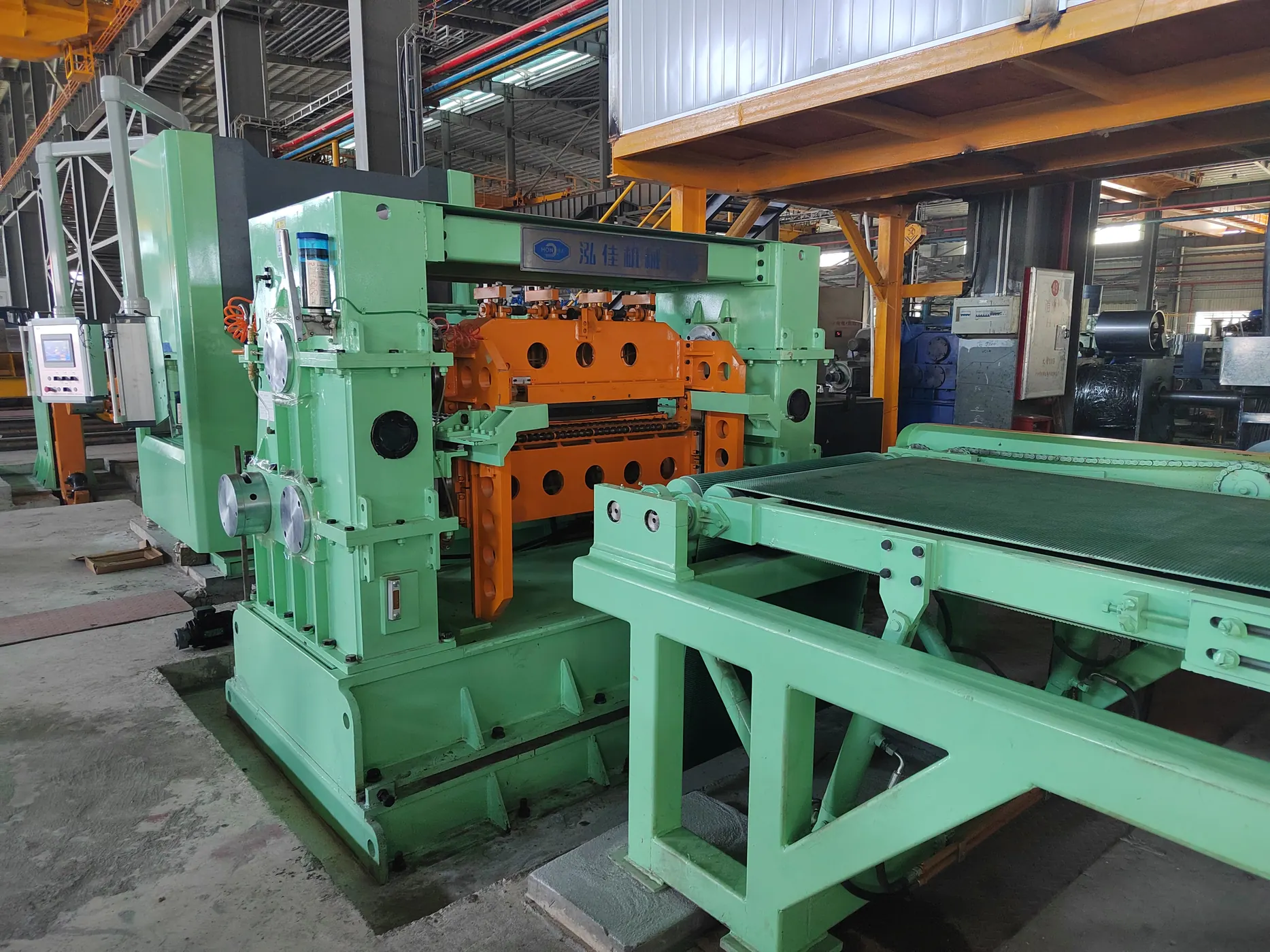
Transferring, stacking and inspecting sheets
The exit section must handle the chosen sheet dimensions and surface condition. Confirm the stacking arrangement, maximum pack requirement and how finished packs leave the line. Surface protection and access for inspection also belong in the layout review.
| Check | State in the requirement | Why it matters |
|---|---|---|
| Length | Nominal length and permitted deviation | Confirms the feed and cut requirement |
| Width | Incoming width and whether trimming is needed | Cross-cutting alone does not define a new width |
| Squareness | Measurement method and permitted deviation | Length alone does not establish rectangular geometry |
| Flatness | Method, support condition and acceptance limit | Separates leveling quality from cut length |
| Surface | Coating, film and acceptable marking | Guides handling and contact-surface review |
Trial-sheet inspection record
Agree the inspection record before a trial. Identify the material, coil, sheet size, trial conditions and the drawing or acceptance document being used. Keep each inspected sheet linked to that record. A permitted length deviation does not automatically define the flatness or surface acceptance requirement.
For each quality check, record the required value or reference, method, instrument, inspection location, observation and decision. Include the units and the person/date responsible for the result. Where the method or limit is unresolved, leave the decision open rather than marking the sheet accepted.
| Inspection field | Record with the result | Question to settle before the trial |
|---|---|---|
| Length and width | Nominal dimensions, individual readings, locations and deviations | Which instrument and locations determine dimensional acceptance? |
| Squareness | The chosen method and its actual readings | Which geometry check and limit does the order require? |
| Flatness | Support condition, inspection area and measured observations | How is the sheet supported and what area is assessed? |
| Surface | Incoming reference, marked locations and processed-sheet photos | Which marks, coating or film conditions are acceptable? |
| Traceability | Coil, sheet, setup, sampling and inspection-document references | Which jobs and samples does the decision cover? |
For an illustrative review, suppose a trial sheet meets the agreed length requirement but flatness has not yet been measured. Record the length result and leave the overall decision open until the remaining requirements are checked. This is an example of using the record, not a measured result or an acceptance limit for MAXDO equipment.
Download the CTL trial-sheet inspection record (CSV). Use separate rows for individual sheets and locations; retain the original readings if a trial is repeated. Review an unexpected result with the equipment supplier using the material and setup record. This checklist does not prescribe shear, feed or leveling adjustments.
Preparing a CTL equipment inquiry
Provide material grade, thickness range, coil dimensions and weight, sheet sizes, accepted tolerances and production mix. Include the smallest and largest regular jobs, not just the maximum dimensions. Confirm every numerical limit against the proposed machine and material.
For an order using gauge notation, identify the material and source table with the sheet thickness reference, then provide the decimal thickness in the inquiry.
Review cut-to-length equipment for the process inquiry, or compare outputs in slitting versus cut-to-length.
Technical reference
Braner USA: Cut-to-Length Lines describes the general feed, leveling and shearing sequence and distinguishes line configurations. Its machine specifications and options are not MAXDO specifications.