High-Speed Stamping Press Coil Feeding Systems 2026
what stamping press operations require from upstream coil processing equipment, how those requirements map to slitting line specifications, and how MaxDo's MD series satisfies those requirements as feedstock preparation equipment.
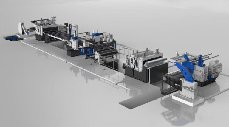
The Coil-to-Press Chain: Why Upstream Processing Determines Press Performance
A stamping press operates at the centre of a production chain that begins long before the ram closes. Before any part is formed, raw coil must be:
- Slit to the precise strip width required by the progressive die or transfer die
- Leveled to remove coil set and residual stress from the coiling process
- Fed into the press at exact pitch, consistent tension, and the correct orientation
Every dimensional error introduced upstream is amplified by the press. A strip width that deviates by 0.3 mm from specification will cause progressive die pilots to contact incorrect positions, generating scrap, damaging tooling, or triggering safety faults on high-speed servo press lines.
This is why the technical specifications of your slitting line and coil feeding system are not secondary to your press investment — they are prerequisites for achieving the press manufacturer’s stated performance levels.
How Stamping Press Speed Defines Coil Processing Requirements
Strokes Per Minute and Strip Feed Rate
High-speed stamping presses operate at speeds measured in strokes per minute (SPM). For each stroke, the feeder must advance the strip by exactly one progressive die pitch before the next stroke. This creates a direct mathematical relationship between press speed and the precision demand on upstream coil preparation:
| Press operating speed | Feed pitch requirement | Strip quality sensitivity |
|---|---|---|
| Low (below 60 SPM) | Moderate | Width tolerance ±0.5 mm typically acceptable |
| Medium (60–150 SPM) | Alta | Width tolerance ±0.2–0.3 mm typically required |
| High (150–400 SPM) | Critical | Width tolerance ±0.1 mm or better; edge condition critical |
| Very high (400+ SPM) | Precision-critical | All upstream parameters at maximum specification |
At high and very high speeds, a single mal-formed strip edge — caused by a dull slitting blade or incorrect blade clearance — can damage progressive die tooling worth tens of thousands of dollars per set within minutes of production.
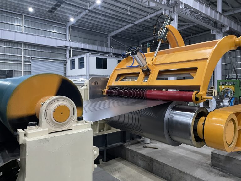
The Loop: Buffer Between Slitting Line and Press
Between the coil straightener/feeder and the press, most production lines include a material loop — a slack section of strip that acts as a buffer against the intermittent, indexed movement of the press versus the more continuous output of the decoiler/straightener system.
Loop control requirements for high-speed operations:
- Loop length must be maintained within a narrow window; excess causes strip to contact the floor or loop guard and buckle; insufficient loop causes tension spikes that disrupt feed pitch
- At higher SPM, loop management requires servo-controlled decoiler drives with rapid response to loop sensor signals
- Strip surface quality at the loop must be maintained: scratches or marks introduced in the loop zone are visible on finished parts for exterior appearance components
The slitting line that produces the strip used in this system must deliver consistent edge geometry (burr height, squareness) and surface condition for the loop to function correctly. An inconsistent edge profile creates friction variations as the strip moves through loop guides, which introduce timing errors in indexed feed systems.
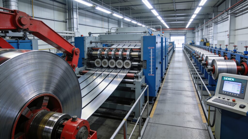
Material Preparation Standards for High-Speed Stamping
Strip Width Tolerance
For progressive die stamping, the strip width tolerance fed into the press directly affects:
- Die pilot location accuracy: Pilots register to strip edges on many progressive die designs
- Blanking symmetry: Off-width strip shifts the blank’s position relative to the die cutting steel
- Part-to-part variation: Width variation becomes dimensional variation in formed features
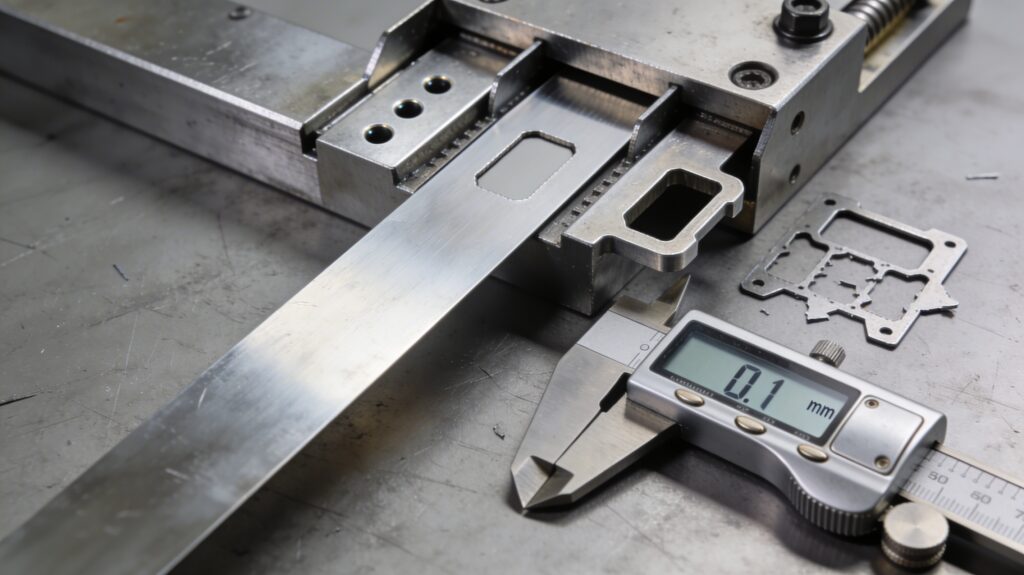
Industry standard for stamping strip width tolerance: ±0.1 mm for automotive exterior and structural components; ±0.2–0.3 mm for general stamping. MaxDo’s MD series is specified at ±0.1 mm slit width tolerance, verified at processing speeds up to 200 m/min on the MD-2200. This meets automotive-grade requirements.
Edge Condition: Burr Height and Squareness
Slitting creates a sheared edge on the strip. The condition of this edge is defined by:
- Burr height: The material that is displaced rather than sheared during cutting. Industry practice is to specify burr height as a percentage of material thickness (typically a maximum of 10% for automotive applications)
- Rollover (rounding at the top of the shear): Affects how strip seats in die pilots and against forming surfaces
- Fracture angle: Affects secondary shear behaviour in progressive blanking operations
Burr height is controlled by two variables: blade clearance (gap between upper and lower slitting blades, expressed as a percentage of material thickness) and blade sharpness. MaxDo’s engineering documentation specifies:
- Steel: 5–8% of material thickness blade clearance
- Aluminium: 3–5% of material thickness blade clearance
Maintaining correct clearance — rather than the most common failure mode of running with excessive clearance as blades wear — is the primary factor in edge quality consistency. MaxDo’s servo-positioning system maintains blade positions at ±0.02 mm repeatability, which means clearance consistency is maintained automatically rather than depending on operator adjustment.
Strip Flatness and Coil Set
Coil set (the residual curvature in strip that has been wound into a coil) must be removed before stamping. Coil set causes:
- Strip to ride up from the die surface between strokes, disrupting pilot registration
- Camber (lateral curvature) that prevents strip from tracking consistently through the die
- Variable forming depth on drawn or embossed features
Flatness correction is performed by the straightener/leveler in the coil handling system between the decoiler and the press feeder. The slitting line’s multi-roll leveling system begins this process: multi-roll leveler configurations reduce material stress variations by 85–90% compared to unleveled material (MaxDoMachine.com, Yield Maximisation documentation), directly improving flatness at the entry to the press line.
For high-strength steel grades — which are increasingly dominant in automotive structural stamping — spring-back after leveling is substantial. Modern coil processing systems incorporate material-specific compensation parameters in recipe management to address this.
MaxDo MD Series as Stamping Line Feedstock Preparation Equipment
MaxDo’s MD series slitting lines are deployed as upstream coil preparation equipment for stamping operations across automotive, appliance, and industrial fabrication supply chains. The specifications that matter specifically for stamping feedstock preparation are:
MD Series Stamping-Relevant Specifications
| Parámetro | MD-850 | MD-1350 | MD-1650 | MD-2200 |
|---|---|---|---|---|
| Slit width output range | 20–820 mm | 300–1,300 mm | 300–1,600 mm | 300–2,150 mm |
| Material thickness (thin gauge) | 0.3–3.0 mm | 0.3–3.0 mm | 0.3–3.0 mm | 0.3–3.0 mm |
| Material thickness (medium gauge) | 1.5–6 mm | 1.5–6 mm | 1.5–6 mm | 1.5–6 mm |
| Material thickness (heavy gauge) | 2–8 mm, 4–12 mm | 2–8 mm, 4–12 mm | 2–8 mm, 4–12 mm | 2–8 mm, 4–12 mm |
| Tolerancia de anchura | ±0,1 mm | ±0,1 mm | ±0,1 mm | ±0.1 mm (verified at 200 m/min) |
| Blade clearance control | Servo ±0.02 mm repeatability | Servo ±0.02 mm repeatability | Servo ±0.02 mm repeatability | Servo ±0.02 mm repeatability |
| Rendimiento del material | 96%+ | 96%+ | 96%+ | 96%+ |
| Compatible materials | MS, SS, Al, Cu | MS, SS, Al, Cu | MS, SS, Al, Cu | MS, SS, Al, Cu |
| Total installed power | ~138.5 kW | ~318.5 kW | ~422.5 kW | ~422.5 kW |
| Certification | ISO 9001 | ISO 9001 | ISO 9001 | ISO 9001 |
Source: MaxDo factory documentation files and MaxDoMachine.com product pages.
Features Critical for Stamping Feedstock Quality
Servo-driven blade positioning (±0.02 mm repeatability): Maintains slit width tolerance across the full working width without manual intervention. This is the primary guarantor of ±0.1 mm strip width for high-speed progressive die operations.
Multi-zone tension control: Prevents strip buckling, camber, and edge wave that would cause feeding errors on high-speed press lines. Entry (150–300 N/mm), processing (80–400 N/mm), and exit (60–150 N/mm) tension zones are managed independently.
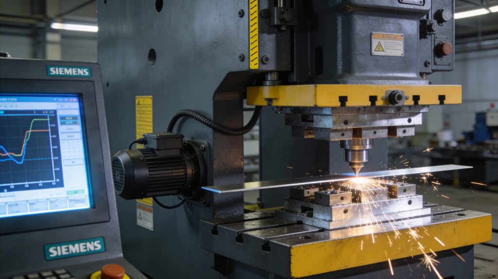
Recipe management — 500+ material specifications: Stamping operations frequently run dozens of material grades and thicknesses. Recipe-based changeover (8–12 minutes versus 45–60 minutes manual) allows the slitting line to respond to production schedule changes without accumulating upstream queues. The Siemens PLC+HMI interface enables recipe import from ERP systems and parameter logging for traceability.
Hydraulic uncoiler with precision recoiler: Consistent tension throughout the uncoiling and recoiling cycle prevents the last-metre quality degradation that is common in manual systems. For high-value automotive materials (stainless, aluminium alloy, pre-coated), this reduces material cost exposure at coil ends.
Automatic coil feeding and recoiling: Reduces operator-introduced variability in coil entry alignment — a common source of camber in manually loaded systems.
📎 Related: MD-850 Product Specifications | MD-1350 Product Specifications | MD-1650 Product Specifications | MD-2200 Product Specifications
Stamping Press Manufacturers — Accurate Category Overview
The following three manufacturers were included in the original version of MaxDo’s supplier comparison article incorrectly categorised alongside slitting line equipment. Each is a leading press manufacturer; none manufactures coil slitting lines. Their interface to MaxDo’s product is as consumers of slit strip produced by coil processing lines — including MaxDo MD series equipment.
Schuler Group (ANDRITZ Schuler) | Germany
Sede central: Göppingen, Baden-Württemberg, Germany
Parent group: ANDRITZ Group
Fundada: 1839
Product scope: Mechanical presses, servo presses (ServoDirect Technology, TwinServo Technology), hydraulic presses, hot-stamping and press-hardening lines, laser blanking lines, transfer automation, coin press systems, digital manufacturing integration (Schuler Digital Suite)
Press force range: 250–32,000 kN
Primary markets: Automotive body and structural components, powertrain components, coin and currency manufacturing, electrical motors
Schuler is one of the world’s largest press manufacturers by scale and technological breadth. Its ServoDirect Technology connects high-torque servo motors directly to the press driveshaft, enabling programmable ram motion profiles that can be optimised per material and per forming operation. This flexibility is particularly valuable for high-strength steel forming, where specific press speed profiles at the bottom of stroke reduce springback and improve part geometry.
Schuler’s Digital Suite connects press operational data (stroke count, force profiles, energy consumption) to production planning and predictive maintenance systems — an Industry 4.0 integration relevant when press downtime creates cascade effects throughout a production schedule.
Coil processing interface: Schuler press lines are fed by coil handling systems (decoilers, straighteners, servo feeders) that typically require slit strip delivered at ±0.1 mm width tolerance for automotive applications. Schuler has also developed its own CTL line technology for direct integration with stamping — for applications where cut blanks are preferable to coil-fed strip. For coil-fed operations, the slitting line producing the feedstock must meet the edge quality and width tolerance standards specified by Schuler’s die engineering team.
For current Schuler press specifications, models, and pricing: schulergroup.com
Note on corporate structure: Schuler Group operates as ANDRITZ Schuler within the ANDRITZ Group. References to “Schuler” and “ANDRITZ Schuler” refer to the same entity.
Aida Engineering | Japan
Sede central: Sagamihara, Kanagawa, Japan
Global operations: North American headquarters in Dayton, Ohio, USA (regional subsidiary — not corporate headquarters)
Product scope: Servo presses (direct-drive), mechanical presses, transfer presses, forging presses, automation systems
Press force range: 1,600–6,000 kN (DSF-U1 series; full range varies by series — verify with Aida)
Primary markets: Automotive body panels, precision metal components, electronics, structural parts
Aida’s defining engineering contribution is its direct-drive servo press architecture, in which a high-torque, low-RPM AC servomotor connects directly to the drive pinion and main gear without intermediate reduction mechanisms. This eliminates the mechanical losses of traditional flywheel-clutch systems, reduces energy consumption at low utilisation rates (the servomotor draws power only during the forming stroke, not continuously as a flywheel does), and enables programmable slide motion with variable velocity at any position in the stroke.
Aida presses feature a highly rigid, symmetrically designed frame (front-to-back) that minimises angular deflection under off-centre loading — important for multi-cavity progressive die operations where individual cavities may have unequal forming forces.
Coil processing interface: Aida press lines in automotive applications typically run high-strength steel (HSS) and advanced high-strength steel (AHSS) grades at strip widths from 100 mm to 1,800 mm depending on part family. These materials require slitting lines with servo blade positioning and closed-loop tension control to maintain dimensional consistency across the strip width — particularly at the edges that contact die pilots. Edge burr height specification for AHSS is typically more stringent than for conventional mild steel, as burrs create stress concentration points in formed features.
For current Aida press specifications: aida-global.com
Correction from earlier article versions: Aida Engineering’s corporate headquarters is in Sagamihara, Kanagawa, Japan — not in Dayton, Ohio, USA. Dayton, Ohio is the location of Aida’s North American regional subsidiary. This distinction matters for buyer sourcing decisions: procurement, engineering support, and OEM relationships are managed from the Japanese headquarters for most global programmes.
Komatsu Industries | Japan
Sede central: Komatsu City, Ishikawa Prefecture, Japan
Note: Komatsu Industries Corporation is a separate company from Komatsu Ltd. (the construction equipment manufacturer), despite sharing the Komatsu name and origin location.
Product scope: Hydraulic presses, mechanical presses, servo presses, automated press systems
Primary markets: Automotive, general metal fabrication, die casting post-processing, household appliances
Komatsu Industries offers both hydraulic and mechanical press technologies. Hydraulic presses provide full-tonnage force throughout the stroke (unlike mechanical presses whose force varies by crank angle), making them preferable for deep drawing, hydroforming, and forming operations that require sustained force application. Mechanical presses offer higher SPM rates suitable for blanking and light forming.
Coil processing interface: Komatsu press lines have similar coil feedstock requirements to other major press manufacturers. The specific tolerance and surface quality requirements depend on the press application and die design. For automotive applications, ±0.1 mm strip width and clean edge condition apply.
For current Komatsu Industries press specifications: komatsu-industries.co.jp
Seven Integration Considerations When Configuring a Coil-to-Press System
Whether you are specifying a new stamping press line with upstream slitting capability, or upgrading an existing slitting line to feed a new high-speed press, the following seven factors determine system compatibility:
1. Strip width range and changeover frequency
The slitting line must cover the full width range required by all die programmes on the press. More importantly, changeover time between strip widths must match production scheduling requirements. A slitting line with 45-minute manual changeovers feeding a press with a 30-minute tool change creates a scheduling constraint that limits production flexibility. MaxDo’s 8–12 minute automated changeover eliminates this bottleneck for most programmes.
2. Material thickness coverage vs. press stroke configuration
The slitting line’s thickness range must match the material specification for all press programmes. High-speed presses are typically configured for a specific thickness range; the upstream slitting line must cover the same or a wider range to avoid limitations on what programmes can be produced. MaxDo’s MD series supports 0.3–12 mm depending on configuration — verify by model against your programme mix.
3. Width tolerance matching to die pilot tolerance
Consult the press tooling specification for pilot registration tolerance. If die pilots are designed for ±0.1 mm strip width variation, the slitting line must deliver strips at that tolerance or better. Running a legacy slitting line with ±0.3 mm actual performance against a die designed for ±0.1 mm will generate pilot registration errors that appear as press faults.
4. Edge condition specification
Define acceptable burr height as a percentage of material thickness for each material grade in your programme mix. Provide this specification to the slitting line supplier and request documentation of how blade clearance management maintains it across a blade service interval. Burr height typically increases as blades wear; servo clearance compensation (as in MaxDo’s MD series) extends the interval between setpoint exceedances.
5. Coil ID and OD at the press entry
The coil handling system at the press (straightener, feeder, pilot release loop) has specific coil inner diameter (ID) and outer diameter (OD) capacity requirements. The slitting line must produce recoiled strip within those dimensional constraints. Coil weight is also a factor: press-side coil car or reel capacity may be lower than the slitting line’s output coil weight, requiring a coil splitting step.
6. Surface quality requirements for the specific application
Exterior appearance parts require coil surface protection throughout the slitting process. Oil film requirements, scratch protection on slitter guides, and rubberised tensioning drums (to prevent marking) are features relevant for automotive exterior programmes. MaxDo’s documentation notes low-friction rubberised tensioning drums for coated and pre-painted materials — confirm configuration requirements with MaxDo application engineering.
7. Traceability and ERP integration
Press quality systems in automotive Tier 1 and OEM facilities require coil-to-part traceability: the heat number and lot number of the raw coil must be linked to every part produced from it. The slitting line’s recipe management and logging system must capture coil ID at entry and propagate it to output coil labels. MaxDo’s PLC+HMI system logs actual vs. programmed parameters per coil run, supporting traceability requirements.
Matching MaxDo MD Series to Press Line Requirements
Use the following selection guide to identify the appropriate MaxDo model based on press line strip width requirements:
| Press line strip width requirement | Recommended MaxDo model | Notes |
|---|---|---|
| Up to 820 mm | MD-850 | Covers narrow-to-medium width range; suitable for HVAC, electronics, and small automotive components |
| 300–1,300 mm | MD-1350 | Mid-range production; covers most automotive body panel strip widths for compact and mid-size vehicles |
| 300–1,600 mm | MD-1650 | Heavy industrial; suitable for full-size automotive, structural, and appliance programmes |
| 300–2,150 mm | MD-2200 | Wide-format processing; covers large automotive body structures, commercial vehicle panels, and industrial plate |
Thickness configuration selection:
Each MD model is configured at order for a specific thickness range (0.3–3.0 mm, 1.5–6 mm, 2–8 mm, or 4–12 mm). Select based on your primary material specification. If your programme mix spans multiple ranges, discuss with MaxDo application engineering whether a configuration optimised for your most critical materials — rather than the widest possible range — is the better approach.
Power infrastructure:
- MD-850: ~138.5 kW total installed power
- MD-1350: ~318.5 kW total installed power
- MD-1650: ~422.5 kW total installed power
- MD-2200: ~422.5 kW total installed power
Verify electrical infrastructure capacity (transformer capacity, incoming supply, earthing) against these figures during facility planning. Installation and commissioning adds 15–25% to equipment cost; include electrical infrastructure upgrades in this estimate.
📎 Related: Líneas avanzadas de corte de metales: 96%+ Rendimiento y Guía completa de ROI
📎 Related: Cómo las líneas de corte longitudinal maximizan el rendimiento del material y reducen los desechos
Preguntas frecuentes
Q: Does a stamping press manufacturer supply the upstream coil processing equipment, or is it sourced separately?
This varies by manufacturer and project scope. Schuler, for example, offers CTL line technology for direct integration with stamping — but this is a separate product line from their press business and is used primarily for blanking operations. For coil-fed progressive die and transfer die operations, the decoiler, straightener, and feeder are typically sourced from coil handling specialists. The slitting line that produces the feedstock coils is almost always a separate purchase from a coil processing equipment manufacturer.
Q: Can the same slitting line serve multiple press lines?
Yes, in most facilities. Slitting lines typically process master coils from the steel service centre or warehouse and produce slit coils that are stored in a finished-coil inventory area, then transferred to individual press lines as needed. The slitting line does not need to be physically adjacent to the press line. This decoupled model also allows the slitting line to run extended high-volume campaigns on common materials, reducing changeover frequency.
Q: What is the lead time impact of sourcing slitting equipment and press equipment from different suppliers?
Both supply chains typically operate on 16–30 week lead times for capital equipment. Coordination of delivery, installation, and commissioning schedules is important: the press line cannot run without feedstock that meets its specification, but installing the slitting line before the press area is ready creates storage and risk issues. Recommend including slitting line commissioning in the press line project schedule from the outset, with a dedicated project milestone for upstream coil processing readiness.
Q: For high-strength steel (HSS / AHSS), what special requirements apply to the slitting line?
High-strength and advanced high-strength steels require higher blade force due to increased material hardness. Blade service intervals are shorter than for conventional mild steel. Spring-back after slitting means edge geometry at the slit face differs from that of conventional steel — blade clearance must be specified correctly for each grade. Recipe management that stores HSS-specific blade clearance and tension parameters (as in MaxDo’s control system) is a requirement rather than a convenience for facilities running mixed material programmes.
Q: What happens if the slitting line produces strips wider or narrower than specified?
Strips that are out-of-specification width should not be fed into a progressive die press. The consequences depend on the error magnitude: small over-width strips will cause die pilots to locate incorrectly, generating part dimensional variation and potentially die damage; under-width strips may cause pilots to miss features entirely, generating scrap and potentially die misfeed faults. Production monitoring systems on modern press lines will detect force anomalies associated with pilot registration errors, but detection comes after damage or scrap has occurred. Prevention — through servo-controlled slitting — is the correct approach.
Q: Does MaxDo provide application engineering support for stamping coil preparation?
Yes. MaxDo offers application engineering consultation to match MD series configuration to specific material programmes and press line requirements. Contact MaxDo’s technical team with your material specification (grade, thickness, width range), production volume requirements, and press line configuration.
Summary — The Upstream Investment Case
High-speed stamping press performance is bounded by the quality of its feedstock. A Schuler ServoDirect press operating at 400 SPM cannot overcome strips that vary ±0.5 mm in width, carry excessive burr, or exhibit camber from poor tension control during slitting.
The ROI case for a MaxDo MD series slitting line in a stamping supply chain includes:
- Yield improvement: 96%+ material yield versus conventional baseline reduces raw material cost per part, which typically represents the largest single cost in the stamping cost model
- Press uptime improvement: Consistent feedstock reduces die pilot damage, unplanned press stops, and die repair cycles
- Quality improvement: ±0.1 mm strip width reduces part-to-part dimensional variation and first-pass inspection rejection rates
- Changeover flexibility: 8–12 minute slitting line changeover supports just-in-time production models by reducing upstream scheduling constraints
MaxDo’s documentation cites payback under 18 months in documented case studies where manual or semi-automated slitting was replaced by MD series equipment — particularly compelling in stamping supply chains where press downtime has high visible cost.
Related Resources
- Top 10 High-Speed Metal Processing Machine Suppliers 2026 — Slitting Line Edition
- Líneas avanzadas de corte de metales: 96%+ Rendimiento y Guía completa de ROI
- Metal Slitting vs. Cut-to-Length Lines: Equipment Selection Guide
- Cómo las líneas de corte longitudinal maximizan el rendimiento del material y reducen los desechos
- Slitting vs. Blanking vs. CTL Lines: Equipment Selection Guide
- The Science Behind Cut-to-Length Precision
- MD-850 Product Page
- MD-1350 Product Page
- MD-1650 Product Page
- MD-2200 Product Page