CTL Lines Complete Guide: Engineering Precision in Cut-to-Length Metal Processing
Comprehensive CTL lines engineering guide covering CT-850, CT-1350, CT-1650 specifications, ±0.1mm precision control, installation requirements, and maintenance protocols. Compare cutting capacities, speeds, and ROI for metal processing operations.
When a metal fabrication shop converts from manual shearing to automated cut-to-length processing, the transformation goes beyond speed improvements. The real value emerges in dimensional consistency that manual operations simply cannot achieve. A properly configured CTL line transforms coiled stock into flat sheets with length tolerances approaching ±0.10mm—precision that becomes critical when those sheets feed into automated welding cells or CNC punch presses where even minor dimensional variance compounds into scrap.
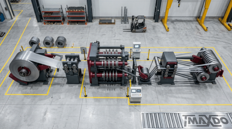
The technology centers on synchronized material handling through five integrated stations: uncoiling, leveling, precision feeding, shearing, and stacking. What distinguishes professional-grade CTL equipment from basic cut-off systems lies in the control architecture. Servo-driven encoders measure strip travel in real-time, triggering shear actuation at exact intervals while maintaining material tension within 2% variance to prevent edge distortion. This level of control enables processing of materials from 0.3mm aluminum foil to 12mm structural steel plate across the same equipment platform.
Material versatility matters because fabrication shops rarely process single gauges. The same line that cuts 1.5mm stainless panels for commercial kitchen equipment might switch to 4mm mild steel for construction brackets by afternoon. MaxdoMachine’s MD-1350 configuration, handling 300-1300mm widths at processing speeds from 1-80 m/min with 318.5kW servo systems, demonstrates this adaptability in mid-volume production environments. The variable speed range accommodates the reality that heavier gauges require slower processing to maintain cut quality and prevent blade shock loading.
Core System Architecture: Beyond Basic Components
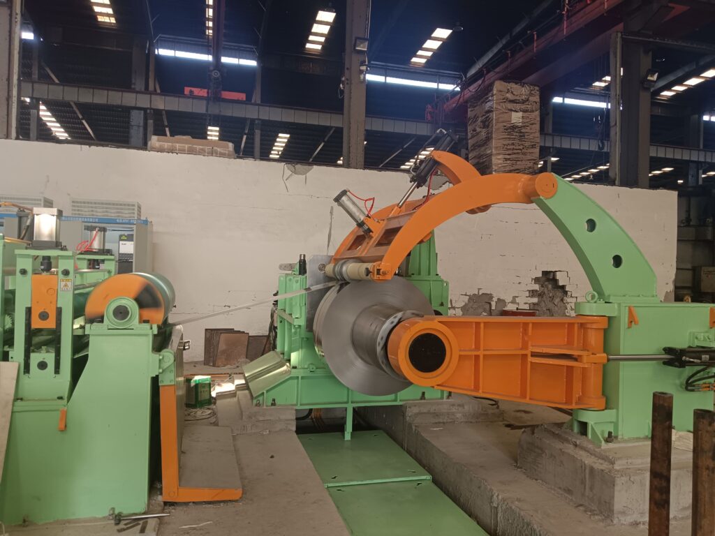
The uncoiler does more than simply rotate—it functions as an active tension management device. Modern servo-driven mandrels adjust rotational resistance dynamically as coil diameter decreases, preventing the tension spikes that cause material stretching in lighter gauges. For operations processing coils up to 35 tons, the uncoiler’s structural rigidity and bearing capacity become mechanical design priorities that directly impact production uptime.

Leveling represents the most technically demanding station in the CTL sequence. Removing coil set requires applying precisely controlled reverse bending that exceeds the material’s yield strength without inducing permanent deformation beyond flatness specifications. Multi-roll leveler configurations use anywhere from 5 to 21 work rolls depending on material thickness and yield strength characteristics. Stainless steel grades with work-hardening behavior demand additional leveling passes compared to mild steel at equivalent thickness.
The precision feeder operates on principles that seem simple until you examine the engineering details. Anti-slip roller surfaces must grip material firmly enough to prevent slippage during acceleration yet avoid surface marking that would reject high-finish stainless grades. Encoder resolution typically measures material travel in 0.01mm increments, with control systems compensating for mechanical compliance in the drive train. This explains why length accuracy deteriorates as lines age—encoder calibration drift and roller surface wear gradually compound into dimensional errors that only systematic maintenance protocols can prevent.
Shearing technology splits into two fundamentally different approaches. Guillotine systems halt material advance, position the strip precisely, then execute a vertical cutting stroke. This stop-start motion limits cycle time but produces cleaner edge quality in heavy gauges above 6mm where shear forces become substantial. Rotary or “flying” shears maintain continuous material flow by using eccentric cam mechanisms that match blade velocity to strip travel during the cutting cycle. The mechanical complexity increases significantly, but throughput for light-gauge material below 2mm can reach 80 m/min—a throughput advantage that justifies the investment in high-volume operations.
Material-Specific Processing Considerations
Aluminum alloys introduce challenges that carbon steel operators often underestimate. The material’s lower density sounds advantageous until you recognize that light coil weight translates to reduced rotational inertia at the uncoiler—meaning tension control requires more aggressive servo response to prevent flutter. Aluminum’s tendency to gum cutting blades necessitates different blade geometries and more frequent resharpening intervals compared to steel processing. A fabricator processing architectural aluminum panels discovered this during commissioning when blade life dropped to 40% of expected values before adjusting rake angles and clearances specific to 5052-H32 alloy.
Stainless steel varieties span mechanical properties ranging from austenitic 304 grades to high-strength martensitic alloys used in spring applications. The work-hardening characteristic of austenitic grades means that material initially entering the leveler at 180 MPa yield strength emerges strain-hardened to considerably higher values. This affects shear blade loading calculations and explains why shops processing predominantly stainless invest in hydraulic shear systems with higher tonnage ratings than equivalent widths cutting mild steel.
Galvanized steel presents surface protection challenges. Excessive leveling pressure cracks or delaminates the zinc coating, creating quality defects that may not appear until the customer’s paint line reveals coating adhesion failures. Conservative leveling parameters preserve coating integrity at the expense of residual coil set that remains within tolerance but approaches the upper limit. The trade-off between absolute flatness and coating preservation requires process knowledge that comes from experience rather than equipment manuals.
MaxdoMachine CTL Line Specifications and Selection Criteria
Equipment capacity must align with both current production requirements and realistic growth projections. Under-specifying width capacity to reduce initial investment creates operational constraints that become expensive to remedy. The MD-850 configuration processing 20-820mm widths suits specialty fabricators handling narrow strips for HVAC ducting, electrical enclosures, and appliance components where material width rarely exceeds 600mm. Power consumption of 138.5kW positions this system for facilities with standard electrical service rather than requiring dedicated transformer installations.
Mid-range production environments processing architectural panels, automotive components, and general fabrication work benefit from the MD-1350’s 300-1300mm width capacity. The 318.5kW power system incorporates sufficient servo motor capacity to maintain processing speeds approaching 80 m/min in gauge ranges from 0.3mm to 3.0mm. Material above 4mm thickness triggers automatic speed reduction to prevent mechanical shock and extend component life—a control strategy that prioritizes equipment longevity over peak throughput numbers.
Heavy industrial applications requiring wide-format processing deploy MD-1650 or MD-2200 configurations. The MD-1650’s 300-1650mm working width handles standard mill coil widths common in steel distribution and heavy fabrication. At 422.5kW total power consumption, these systems demand three-phase electrical infrastructure typically found in industrial facilities rather than light manufacturing environments. The MD-2200 extends working width to 2150mm, accommodating full-width primary mill coils for operations like service centers that process material directly from steel producers.
Coil weight capacity across all MD configurations spans 10-35 tons with customization available for specialized applications. The customization aspect matters more than it might appear—a fabricator processing predominantly 15-ton coils gains nothing from uncoiler capacity rated to 35 tons except unnecessary capital expense and floor space consumption. Properly specified equipment matches actual production requirements rather than theoretical maximum capabilities.
Installation Planning: Foundation Through Commissioning
Foundation engineering requirements scale with equipment mass and dynamic loading. The MD-850’s comparatively compact footprint reduces civil engineering demands, but even this configuration generates substantial instantaneous loads during shearing cycles. Concrete pads must be designed for dynamic loading conditions, not just static equipment weight. Anchor bolt patterns require surveying to tolerances within 2mm to ensure proper equipment alignment—a requirement that general contractors frequently underestimate until commissioning reveals alignment issues affecting cut quality.
Electrical infrastructure extends beyond simple kVA calculations. Servo drive systems generate harmonic distortion on power lines that can affect sensitive electronic equipment elsewhere in the facility. Power quality analysis prior to installation identifies potential issues requiring harmonic filtering or dedicated electrical service. Emergency stop circuits must integrate across all stations with redundant safety interlocks meeting OSHA 29 CFR 1910.212 machine guarding requirements. Facilities operating in jurisdictions with additional safety regulations face extended commissioning timelines if electrical systems require modification to achieve compliance.
Pneumatic systems supply compressed air for blade actuation, tension controls, and safety interlocks. Air quality matters more than many operators recognize—moisture and particulate contamination in compressed air systems cause valve failures that manifest as inconsistent shear timing or tension control instability. Installing dedicated air dryers and filtration specifically for CTL equipment prevents maintenance issues that compromise production reliability.
Commissioning typically requires 2-4 weeks depending on system complexity and operator training requirements. This timeline assumes properly prepared foundations, complete electrical infrastructure, and material availability for test runs. Facilities attempting to compress commissioning schedules by running production material during setup risk creating quality issues that persist long after the equipment supplier departs. The MD-1350 installation at a Vietnamese electronics manufacturer required additional calibration time specifically for the 0.8mm aluminum alloy used in device housings—material properties that demanded refined tension control settings beyond initial configuration.
Operational Procedures That Actually Work
Coil loading procedures sound straightforward until you watch an inexperienced operator struggle with threading 1.5mm stainless through the leveler while maintaining proper edge tracking. Material edge condition matters—slit coils with burrs or damaged edges require de-burring before threading to prevent tracking problems that cause edge damage accumulating through the process. Some operations install dedicated edge conditioning equipment specifically to improve first-pass threading success rates.
The PLC interface might display cut length entry as a simple numeric input, but the underlying control logic compensates for multiple mechanical factors. Material elastic recovery after leveling affects actual finished length, requiring offset values that vary by material grade and thickness. A 2000mm programmed length in 2.5mm mild steel produces different actual finished dimensions than the same programmed length in 2.5mm 304 stainless due to differences in elastic modulus and work-hardening response. Operators who understand material behavior rather than simply following setup sheets achieve better dimensional consistency.
Quality verification extends beyond measuring finished length with a tape measure. Flatness measurement across the sheet width reveals leveling effectiveness—crowned sheets indicate insufficient leveling pressure while edge-wavy material suggests excessive tension or inadequate strip guidance. Squareness measurement using precision squares identifies shear blade misalignment that might exist within acceptable limits for rough fabrication but causes rejection in precision applications. The distinction between general fabrication tolerances and precision manufacturing requirements shapes quality verification protocols.
Production changeovers consume time that doesn’t appear in processing speed specifications. Switching from 1.2mm galvanized to 3.0mm stainless requires leveler adjustment, tension recalibration, shear blade gap verification, and control system parameter updates. Facilities processing diverse materials benefit from documented setup procedures specific to common material grades rather than relying on operator memory or generic instruction manuals. One Midwestern fabricator reduced average changeover time from 65 minutes to 28 minutes simply by creating material-specific setup sheets stored at the operator station.
Maintenance Strategies Based on Actual Failure Modes
Daily inspection routines focus on indicators of developing problems rather than comprehensive system checks. Unusual noise from the uncoiler bearings signals potential failure weeks before catastrophic seizure—catching this early means scheduling replacement during planned downtime rather than scrambling for overnight bearing procurement. Hydraulic fluid discoloration indicates contamination or thermal degradation requiring fluid analysis before component damage occurs. These subtle indicators separate operations that maximize uptime from those experiencing frequent unexpected failures.
Leveler roll condition directly affects flatness quality but deteriorates gradually rather than suddenly. Measuring roll crown using precision micrometers reveals wear patterns before they produce obvious quality defects. Shops processing abrasive materials like galvanized steel or aluminum with hard surface oxide layers need more frequent roll inspection than those running predominantly cold-rolled steel. Roll refurbishment timing becomes an economic decision—operating with slightly worn rolls risks quality issues while premature replacement wastes remaining roll life.
Shear blade maintenance intervals depend heavily on material characteristics and production volume. Hardened tool steel blades processing mild steel might achieve 50,000 cuts before requiring resharpening, while the same blades cutting high-strength steel experience wear rates 3-4 times higher. Blade clearance adjustment compensates for wear initially, but eventually edge quality deteriorates to the point requiring resharpening regardless of dimensional settings. Some operations maintain spare blade sets specifically to avoid production interruptions during blade service.
Encoder calibration drift affects length accuracy gradually enough that operators might not notice until customer complaints trigger investigation. Establishing routine verification using calibrated length standards—a practice borrowed from machine tool maintenance—catches calibration drift before it produces scrap. The verification process takes 15 minutes but prevents the expense of scrapping an entire production run cut 5mm short because encoder calibration shifted over six months of operation.
Practical Troubleshooting: Symptoms and Root Causes
Length tolerance problems manifest in different patterns that indicate specific failure modes. Consistent short lengths suggest encoder calibration error or systematic control offset. Random variation in finished length points to feed roll slippage or inconsistent material properties. Progressive length change over a production run often indicates uncoiler tension variation as coil diameter decreases. Diagnosing the actual root cause rather than adjusting control parameters to compensate prevents creating new problems while addressing symptoms.
Edge quality defects beyond simple burr formation reveal blade condition and shear geometry issues. Ragged edges with tearing indicate dull blades or excessive blade clearance. Edge rollover suggests insufficient blade rake angle for the material being processed. Secondary shearing—a faint line parallel to the cut edge—results from blade geometry mismatch or vibration during the cutting stroke. These distinctive failure modes guide troubleshooting more effectively than generic “poor cut quality” observations.
Flatness problems after leveling require distinguishing between coil set that wasn’t removed and new distortion introduced by the leveling process itself. Material exiting the leveler with consistent crown across the width indicates insufficient leveling pressure or incorrect roll configuration for the material thickness. Edge waviness developing in previously flat material suggests excessive tension between leveler and feeder or temperature-related expansion in asymmetric patterns. The corrective action differs completely depending on which mechanism causes the defect.
Vibration at operating speed presents mechanical rather than control system issues. Unbalanced rotating components in the uncoiler or recoiler create speed-dependent vibration that intensifies as RPM increases. Structural resonance occurs when mechanical natural frequencies align with operating speeds—a problem requiring either speed adjustment or structural damping modifications. Bearing wear generates vibration patterns that worsen progressively, providing advance warning before failure if monitoring systems detect the characteristic frequencies.
Safety Systems: Engineering for Human Behavior
Guard interlocks sound like simple on-off switches until you examine human factors in actual production environments. Operators under production pressure develop creative methods to bypass safety systems that slow material threading or maintenance access. Properly engineered safety systems balance access requirements with protection, using sequential interlocks that prevent simultaneous access to hazardous zones rather than blanket lockouts that operators circumvent. The light curtains around shear zones detect intrusion and trigger immediate stops, but their placement must account for legitimate operator positions during normal operation.
Emergency stop systems require Category 4 safety architecture with monitored circuits that detect internal failures. Simple E-stop buttons without monitoring might fail in the exact emergency situation they’re intended to prevent—a failure mode that regulatory investigations after workplace accidents consistently identify. The redundancy costs more initially but proves worthwhile when a genuine emergency occurs and the system functions as designed rather than failing silently.
Lockout-tagout procedures govern maintenance activities, but effective LOTO requires specific knowledge of energy storage points beyond obvious electrical disconnects. Hydraulic accumulators maintain pressure that can cause unexpected motion during maintenance. Pneumatic systems store energy in receiver tanks and valve manifolds. Mechanical energy exists in elevated components or loaded springs. Comprehensive LOTO procedures identify every energy source rather than assuming that pulling the main electrical disconnect creates a zero-energy state.
Personal protective equipment requirements adapt to specific hazards rather than applying universal standards. Cut-resistant gloves protect during blade changes but introduce entanglement hazards near rotating equipment. Safety glasses adequate for general fabrication don’t provide sufficient impact protection during hydraulic system maintenance where high-pressure fluid injection injuries occur. Hearing protection becomes mandatory in facilities running multiple lines where cumulative noise exposure exceeds 85 dBA despite individual equipment components measuring below threshold.
Real-World Implementation: What Actually Happens
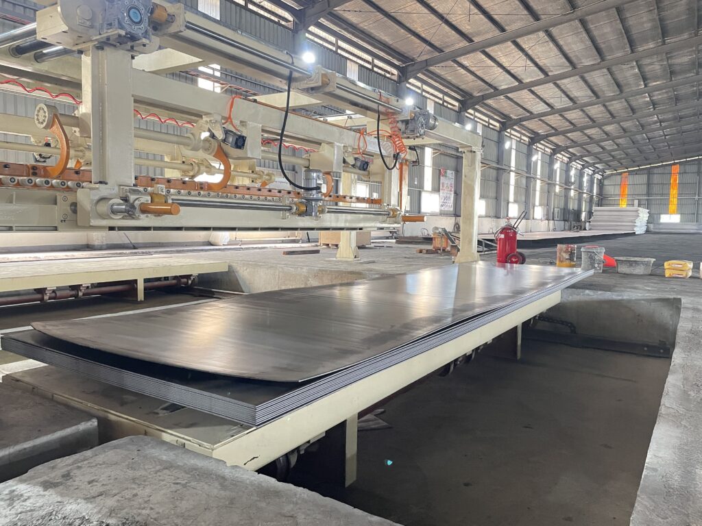
A mid-sized fabricator in Ontario transitioned from manual shearing to an MD-1350 CTL line specifically to support a contract requiring 10,000 sheets weekly with ±0.2mm length tolerance. The equipment easily met technical specifications, but production struggled initially because material handling systems couldn’t keep pace with CTL line output. The bottleneck shifted from cutting capacity to stacking and bundling—a logistics problem that equipment specifications don’t reveal. They eventually installed automated stacking with conveyor transfer to separate bundling stations, increasing effective throughput by 40% without touching CTL line settings.
An automotive supplier processing predominantly 1.5mm cold-rolled steel discovered that material coil set varied significantly between steel mills despite identical grade specifications. This variation manifested as inconsistent flatness that required leveler adjustment for each coil supplier. Their solution involved logging leveler settings by mill supplier and heat number, creating an empirical database that operators referenced during setup. This practical knowledge system reduced trial-and-error setup time from 30 minutes to under 10 minutes for familiar material sources.
A service center installing an MD-2200 for wide-coil processing underestimated floor loading capacity in their existing facility. The 35-ton coil capacity combined with equipment mass exceeded the building’s structural rating when fully loaded. They ended up reinforcing the foundation and adding structural steel columns—a $60,000 cost that proper engineering assessment during equipment selection would have identified. The lesson resonates: equipment specifications matter less than system integration into actual facility constraints.
Selecting Between Continuous and Intermittent Cutting
Flying rotary shears justify their complexity in high-volume operations processing lighter gauges where throughput drives profitability. The continuous motion eliminates acceleration-deceleration cycles that limit guillotine system productivity, but the mechanical complexity introduces maintenance requirements that smaller operations struggle to support. A rotary shear installation might require specialized service from the equipment supplier rather than in-house maintenance capabilities—a dependency that creates operational risk if response times extend during breakdowns.
Guillotine shears suit operations where cut quality matters more than cycle time, particularly in heavy gauges above 6mm. The stopped material and vertical blade motion produce cleaner edges with less distortion than continuous cutting methods. For fabricators supplying precision-ground blanks or laser cutting operations where edge quality affects subsequent processing, guillotine configuration delivers superior results despite lower throughput. The decision ultimately reflects production priorities rather than absolute technical superiority of either approach.
Material thickness substantially affects the selection criteria beyond simple cutting force calculations. Thin gauges below 1mm benefit from continuous processing that maintains material tension preventing flutter and edge distortion. Heavy plates above 8mm require the controlled blade engagement that guillotine systems provide, preventing shock loading and excessive blade wear. The material thickness range your operation actually processes—not theoretical equipment capability—should drive the cutting system configuration decision.
About MaxdoMachine
Foshan Maxdo Machine brings 20+ years of metal processing equipment engineering to manufacturers across automotive, HVAC, construction, and appliance industries. Our MD-series CTL configurations from compact 820mm to wide-format 2150mm systems deliver the precision-to-throughput balance that production environments demand. Technical support extends from initial facility surveys through installation commissioning and operational training, ensuring equipment integration matches your specific production requirements. For detailed specifications on MD-1350 mid-range CTL systems or MD-1650 heavy-duty configurations, contact our application engineering team to discuss your material processing requirements.