Medium-Gauge Blanking Lines: Professional Guide to Precision Cut-to-Length Systems
Medium-gauge blanking lines transform metal coils ranging from 1.5mm to 12mm thickness into precision-cut flat sheets through automated uncoiling, leveling, measuring, and shearing operations. Unlike slitting lines that produce narrow-width continuous coils, blanking systems—also called cut-to-length (CTL) lines—deliver fixed-length sheets at programmed dimensions with length accuracy reaching ±0.1mm for demanding fabrication applications. This thickness spectrum addresses the critical gap between light-gauge high-speed processing and heavy structural plate cutting, serving automotive stamping operations, HVAC component fabrication, appliance panel production, and architectural metal manufacturing where both material thickness capacity and dimensional precision determine production viability.
Understanding Medium-Gauge Processing Requirements
The medium-gauge classification encompasses material thicknesses from 1.5mm through 12mm, representing the majority of industrial sheet metal applications worldwide. This range includes common carbon steel gauges from 14-gauge (1.9mm) down to 3-gauge (6mm), stainless steel from 16-gauge (1.5mm) to 1/4-inch (6.35mm), and aluminum alloys spanning similar dimensional territories. Processing these thicknesses demands equipment engineered to remove coil set memory—the curvature retained from coil winding—while maintaining flatness tolerances typically specified at 0.5mm deviation per meter of length.
Material characteristics within this thickness band create distinct processing challenges compared to thinner gauges. Elastic springback increases proportionally with thickness, requiring leveling systems capable of inducing plastic deformation through multiple bending cycles. Thicker materials also exhibit greater resistance to shearing forces, necessitating hydraulic guillotine systems with blade tonnage capacities calculated at approximately 40-60 tons per meter of cutting width for mild steel, with proportional increases for higher-strength alloys.
The economic justification for dedicated medium-gauge blanking equipment centers on eliminating outside processing costs while improving material utilization and production scheduling flexibility. Facilities processing 50 tons or more monthly in this thickness range typically achieve 12-18 month equipment payback through combined savings in material yield improvement, transportation cost elimination, and lead time reduction.
Cut-to-Length Process Fundamentals
Decoiling and Tension Management
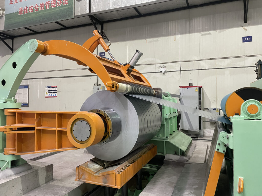
The blanking sequence begins with coil loading onto a motorized decoiler equipped with expandable mandrels that grip the coil inner diameter, typically ranging from 508mm to 610mm for industrial coil stock. Servo-controlled motors rotate the mandrel in precise synchronization with downstream material consumption, maintaining tension values between 5-12% of material yield strength to prevent buckling without inducing plastic elongation that would compromise dimensional accuracy.
Tension control systems employ load cells positioned between the decoiler and entry section, measuring instantaneous force and transmitting feedback to the servo drive controller that adjusts rotational velocity within milliseconds. This closed-loop regulation becomes critical when processing coils exhibiting thickness variation across width—a common condition in hot-rolled materials where center and edge gauges may differ by 0.05-0.15mm. Advanced systems incorporate edge position sensors that detect lateral coil drift, triggering automatic steering corrections to maintain centerline alignment through the leveling and shearing stations.
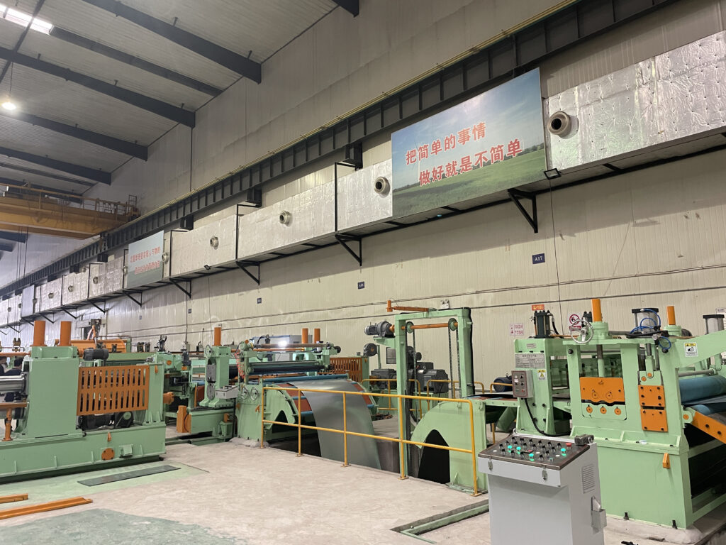
Precision Leveling Technology
Leveling represents the most critical operation in blanking line processing, determining final flatness characteristics that enable fabricated parts to meet stamping die clearances and assembly tolerances. Multi-roll levelers contain 13 to 21 work rolls alternately positioned above and below the material plane, creating controlled bending moments that exceed the material’s yield point in both tension and compression. Each bending cycle progressively reduces residual stress, with the number of rolls and their diameter determining leveling effectiveness for specific material properties.
Roll diameter selection follows engineering principles balancing bend radius against material thickness and yield strength. Medium-gauge materials typically employ roll diameters from 120mm to 180mm, with larger diameters suited for thicker gauges and smaller diameters providing the aggressive bending necessary for work-hardening alloys like 301 and 304 stainless steel. Roll spacing—the distance between adjacent roll centers—ranges from 150mm to 250mm, with tighter spacing increasing the number of bending cycles per unit length and thereby improving stress relief.
Adjustable roll penetration allows operators to fine-tune leveling intensity based on observed material condition. Typical penetration adjustments range from 2mm to 8mm of vertical displacement between entry and exit rolls, with excessive penetration risking surface marking on soft materials and insufficient penetration failing to remove coil set from high-yield-strength alloys. Experienced operators calibrate penetration through iterative testing, measuring exit flatness with precision straightedges or laser profiling systems.
Servo Feed and Measurement Systems
Following leveling, material advances through servo-controlled feed mechanisms that position sheets at programmed cutting lengths with repeatability exceeding ±0.1mm over extended production runs. Two primary feed technologies dominate medium-gauge applications: continuous servo roll feeders with accumulator loops, and intermittent grip feed systems employing hydraulic clamps.
Servo roll systems maintain constant material contact through opposed pinch rolls driven by AC servo motors equipped with high-resolution encoders measuring angular position at 1,000,000 pulses per revolution or greater. This encoder resolution translates to linear measurement accuracy of 0.01mm, enabling the tight length tolerances demanded by automotive and appliance fabricators. Material advancement continues during leveling operations, with accumulator sections—typically S-shaped or loop configurations—storing excess material during the brief shearing cycle when feed momentarily stops.
Grip feed mechanisms employ hydraulic clamps that close on the material surface, advance a programmed distance, release, and retract for the next cycle in synchronization with the shearing operation. While slower than continuous servo systems, grip feeds provide superior control for thick materials prone to slippage in roller systems and eliminate the need for accumulator sections that extend overall line length. Processing speeds with grip systems typically range from 30-60 m/min for medium-gauge materials, compared to 60-100 m/min achievable with servo roll configurations.
Guillotine Shearing Mechanics
Hydraulic guillotine shears dominate medium-gauge blanking applications due to their ability to produce clean cuts through materials up to 12mm thickness without secondary edge finishing. The shearing mechanism involves a hardened tool steel upper blade descending past a stationary lower blade at velocities typically ranging from 100-300 mm/second, with blade overlap and clearance determining cut quality.
Blade clearance—the horizontal gap between upper and lower cutting edges at the moment of material fracture—critically affects edge condition. Proper clearance for medium-gauge steel typically measures 6-8% of material thickness, translating to 0.12-0.16mm for 2mm stock and 0.36-0.48mm for 6mm material. Insufficient clearance causes secondary shearing as the upper blade forces material past the lower blade rather than initiating clean fracture, resulting in doubled edges and excessive burr formation. Conversely, excessive clearance allows material to bend excessively before fracture initiates, producing ragged edges requiring deburring operations.
Blade rake angle—the geometric inclination of the upper blade relative to horizontal—reduces peak shearing force by distributing cutting action progressively across the material width. Typical rake angles range from 0.5 to 2.0 degrees, with thicker materials benefiting from larger angles that extend cutting time while decreasing instantaneous force requirements. A 1,300mm-wide blanking line cutting 6mm mild steel with 1.5-degree rake angle experiences peak shearing forces approximately 35% lower than equivalent zero-rake configurations, reducing hydraulic system demands and extending structural component fatigue life.
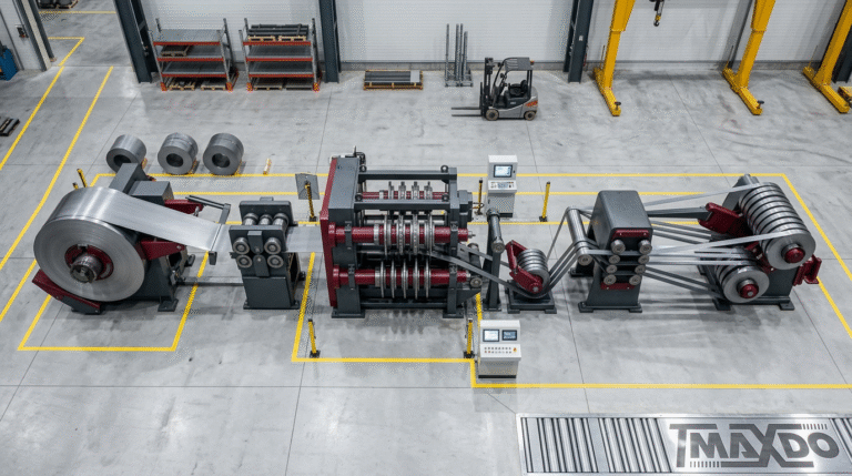
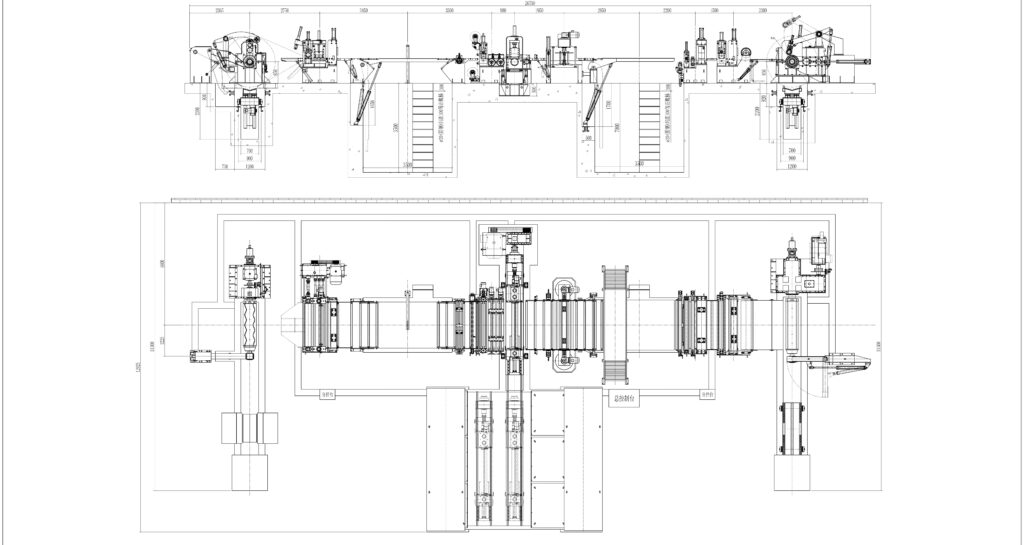
MaxdoMachine Cut-to-Length Solutions
Cutlength-850: Compact Medium-Gauge Platform
The Cutlength-850 system addresses facilities requiring medium-gauge processing capability within constrained floor space, handling material widths from 300mm to 820mm across the complete thickness spectrum from 0.3mm light-gauge up through 12mm maximum capacity. Processing velocity reaches 60 m/min for lighter materials within the medium-gauge range, with speeds decreasing proportionally as thickness increases to maintain shearing quality and leveling effectiveness.
This configuration suits HVAC duct fabrication shops processing galvanized steel from 0.8mm to 1.5mm thickness, appliance panel manufacturers working with pre-painted steel and stainless materials from 0.6mm to 2.5mm, and electrical enclosure producers requiring precision blanks in cold-rolled steel from 1.0mm to 3.0mm thickness. Coil weight handling spans 10 to 35 metric tons through adjustable decoiler configurations, enabling facilities to balance coil purchasing economics against changeover frequency.
Installation footprint typically measures 16-19 meters in length and 3.5-4.0 meters in width, with 5-meter minimum ceiling height required for overhead coil handling systems. Foundation requirements specify 350mm minimum concrete thickness with 28-day compressive strength exceeding 25 MPa and embedded anchor systems designed for equipment mass plus dynamic loading from shearing operations.
CT-1350: Mid-Range Production Workhorse
Expanding processing capability to 1,300mm maximum width, the CT-1350 configuration serves mid-volume fabrication operations processing 100-300 tons monthly across diverse material grades and thicknesses. The system operates at speeds reaching 80 m/min for medium-gauge materials, with power consumption of 136kW supporting the hydraulic, servo, and leveling systems necessary for wider material processing.
Automotive tier suppliers employ CT-1350 systems for producing stamping blanks in advanced high-strength steels (AHSS) ranging from 1.5mm to 4.0mm thickness, where precise length control and superior flatness enable direct feeding into progressive stamping dies without secondary preparation. Construction component manufacturers utilize similar equipment for architectural panel blanking in pre-finished aluminum and stainless steel from 1.0mm to 3.0mm, where surface quality preservation during leveling and cutting operations determines final product acceptance.
The increased width capacity enables processing of master coils in standard 1,219mm (48-inch) and 1,250mm (49-inch) dimensions common in North American and European steel markets, reducing material costs through volume purchasing while maintaining production flexibility for narrower finished blanks. Dual coil mandrel systems optionally available on this platform reduce changeover downtime to 5-7 minutes by enabling pre-threading of subsequent coils while current material processes.
CT-1650: Heavy-Width Medium-Gauge Capability
For applications demanding maximum width capacity within the medium-gauge thickness range, the CT-1650 handles materials from 300mm to 1,650mm width while maintaining identical thickness capabilities through 12mm maximum. Processing speeds mirror the CT-1350 at 1-80 m/min, with actual production velocity dependent on material properties and required flatness specifications.
Construction panel fabrication represents a primary application, where 1,500mm-wide architectural cladding panels in 1.5mm to 2.5mm aluminum or steel require the combination of width capacity and medium-gauge processing capability. Shipbuilding and marine applications similarly benefit from this configuration when processing corrosion-resistant alloys including 316L stainless steel and 5083 aluminum in thicknesses from 4mm to 8mm for structural components and deck panels.
The wider processing envelope demands proportionally increased structural rigidity to maintain cutting accuracy and flatness specifications across the full width. Leveling systems incorporate 17-21 work rolls with diameters reaching 180-200mm to provide the bending moment necessary for removing coil set from wide materials while minimizing deflection under load.
Application Engineering and Optimization
Material-Specific Processing Parameters
Different alloy families within the medium-gauge thickness range demand distinct processing parameters to achieve optimal results. Aluminum alloys including 3003-H14, 5052-H32, and 6061-T6 require blade clearances reduced to 4-6% of material thickness compared to steel’s 6-8% specification, preventing the tearing and ragged edges that aluminum’s lower ductility promotes. Leveling roll pressures similarly decrease by 30-40% relative to equivalent steel thicknesses to prevent surface impressions in aluminum’s softer matrix.
Stainless steel grades present opposite challenges, with work-hardening characteristics demanding increased leveling intensity and modified shearing parameters. Austenitic grades including 304 and 316 exhibit yield strengths 30-50% higher than comparable carbon steel, requiring deeper leveling roll penetration and additional bending cycles to remove coil set effectively. Blade clearances increase to 8-10% of material thickness to accommodate stainless steel’s greater ductility and tendency toward work hardening during the shearing process itself.
Advanced high-strength steels (AHSS) with yield strengths exceeding 550 MPa challenge conventional medium-gauge blanking equipment designed for mild steel processing. These materials demand maximum leveling capacity, with some applications requiring pre-leveling passes or increased roll diameters beyond standard configurations. Shearing AHSS generates accelerated blade wear, often necessitating tool steel blade materials with hardness ratings of 58-62 HRC compared to 52-56 HRC sufficient for mild steel.
Production Rate Maximization Strategies
Optimizing blanking line throughput requires balancing material changeover frequency against run lengths for individual specifications. Facilities processing diverse thickness ranges benefit from organizing production schedules in ascending thickness order, minimizing leveling adjustments compared to random-order fulfillment. A typical week’s production might sequence 1.5mm materials on Monday, 2.5-3.0mm Tuesday through Wednesday, 4-6mm Thursday, and 8-12mm Friday, with single leveling recalibration between thickness bands rather than continuous adjustment.
Coil weight selection impacts productive efficiency through the ratio of processing time to changeover downtime. Maximum 35-ton coils minimize changeovers but require extended setup periods and create schedule inflexibility, while lighter 15-ton coils enable responsive order fulfillment at the cost of increased nonproductive time. Mathematical optimization for a facility processing 200 tons monthly across mixed specifications typically indicates optimal coil weights around 20-25 tons, balancing setup efficiency against scheduling agility.
Automated parameter storage systems reduce setup time from 15-20 minutes manual adjustment to 3-5 minutes automated recall for frequently processed materials. Modern PLC systems store leveling roll positions, feed lengths, shearing blade clearances, and material handling parameters for hundreds of unique specifications, enabling single-button changeover between common grades.
Maintenance Protocols for Sustained Performance
Daily inspection routines focus on components directly affecting product quality, including leveling roll surface condition, shear blade edges, and feed system alignment. Operators examine leveling rolls for scoring or surface defects that transfer impressions to processed material, with portable surface roughness testers quantifying roll condition when visual inspection proves inconclusive. Shear blade inspection identifies edge wear, chipping, or heat discoloration indicating dull cutting surfaces requiring rotation or replacement.
Weekly maintenance encompasses lubrication schedules for bearing housings, gear reducers, and hydraulic cylinder rod surfaces using manufacturer-specified greases and oils applied at documented intervals. Tension system calibration verification ensures load cell readings correspond to actual material tension, with periodic testing using calibrated weights or hydraulic load cells confirming measurement accuracy within ±2%. Hydraulic system cleanliness monitoring through periodic oil sampling detects contamination before component damage occurs, with ISO 4406 cleanliness codes maintained at 18/16/13 or better for medium-pressure systems.
Monthly procedures include detailed inspection of drive chains, coupling alignment, and structural components for signs of fatigue or wear. Electrical system checks verify proper operation of safety interlocks, emergency stops, and motion control feedback devices, with resistance measurements on grounding conductors ensuring personnel protection systems remain functional. Precision measurement of leveling roll parallelism using dial indicators or laser alignment systems detects gradual misalignment before processing quality degrades noticeably.
Quality Troubleshooting and Resolution
Length Dimension Accuracy Issues
When finished blanks exhibit length variations exceeding specification tolerances, systematic diagnosis begins with encoder calibration verification. Servo feed systems employ rotary encoders measuring material advancement through pinch roll rotation, with calibration factors translating angular displacement to linear distance. Comparing measured lengths against precision reference standards using calibrated steel tapes or laser measurement devices quantifies encoder accuracy, with deviations exceeding 0.15mm over 3-meter test lengths indicating calibration drift requiring controller adjustment.
Material slippage between feed rolls produces length inconsistencies characterized by random variation rather than systematic offset. Insufficient pinch pressure, worn roll surfaces, or oil contamination on roll faces all enable slippage, correctable through hydraulic pressure adjustment, roll resurfacing, or solvent cleaning respectively. Testing under production loads while monitoring encoder counts versus actual material advancement confirms whether slippage contributes to dimensional problems.
Elastic springback in high-yield-strength materials can cause apparent length errors when sheets relax after cutting, particularly in AHSS grades with yield strengths exceeding 700 MPa. This phenomenon manifests as consistent dimensional shortening proportional to material yield strength and thickness, correctable through programming length offsets that compensate for predictable contraction.
Edge Quality Optimization
Excessive burr height—the raised edge remaining after shearing—indicates improper blade clearance, dull cutting edges, or incorrect shearing velocity. Blade clearance verification using feeler gauges at multiple points across the shear width identifies non-uniform gaps requiring mechanical adjustment of blade parallelism. Clearance reduction typically resolves burr issues, progressing in 0.05mm increments until burr height falls within specification, commonly 0.10mm maximum for medium-gauge materials.
When proper clearance fails to eliminate excessive burrs, blade condition inspection becomes necessary. Worn blades exhibit rounded cutting edges visible under 10x magnification, with edge radius exceeding 0.05mm indicating replacement requirements. Blade rotation to fresh cutting edges typically restores quality immediately, confirming wear as the root cause.
Ragged or torn edge characteristics suggest excessive blade clearance allowing material to deform excessively before fracture initiates. Clearance reduction resolves this condition, though careful incremental adjustment prevents overcorrection into the burr-generating clearance range. Some materials exhibit narrow optimal clearance windows requiring precision adjustment and documentation of successful settings for future reference.
Industry Standards and Safety Compliance
Medium-gauge blanking lines must incorporate comprehensive machine guarding preventing operator access to pinch points, shearing zones, and rotating components during operation per OSHA 29 CFR 1910.212 requirements. Light curtain systems positioned at entry and exit sections detect personnel intrusion, immediately stopping material motion while maintaining hydraulic brake engagement to prevent drift. Interlocked access gates on leveling and shearing sections enable maintenance access while ensuring automatic shutdown when opened during operation.
Emergency stop systems require positioning at maximum 10-meter intervals along line length, enabling operators to halt equipment from any work position within two-second access time. E-stop circuits must interrupt power to all motion-producing components within 0.5 seconds of activation while engaging mechanical brakes to prevent material movement. Monthly testing of emergency stop functionality verifies response time and brake engagement, with documented results required for OSHA compliance audits.
Lockout-tagout procedures govern all maintenance activities requiring access to hazardous zones, mandating complete isolation of electrical, hydraulic, and pneumatic energy sources before personnel entry. Written procedures specific to each maintenance task prevent premature equipment energization, with multi-lock hasps enabling simultaneous lockout by multiple maintenance personnel during complex repairs.
Conclusion: Strategic Equipment Selection
Selecting appropriate medium-gauge blanking equipment requires analyzing material specifications, production volumes, quality requirements, and facility constraints against available system configurations. The Cutlength-850 serves compact operations processing materials to 820mm width, the CT-1350 addresses mid-range requirements to 1,300mm, and the CT-1650 provides maximum 1,650mm capability for wide-format applications.
Understanding the fundamental differences between cut-to-length blanking systems and slitting lines enables informed decisions matching equipment capabilities to actual production requirements. For comprehensive insights into optimizing CTL line operations, including precision techniques and efficiency strategies, manufacturers gain competitive advantages through proper equipment specification and operation.
Success in medium-gauge blanking demands attention to processing fundamentals, material-specific parameters, preventive maintenance protocols, and continuous optimization of operational procedures that collectively determine equipment performance across 15-20 year service lifecycles.