CTL Lines vs. Slitting Lines: A 2026 Guide to Choosing the Right Coil Processing System
Engineering managers' guide to CTL vs slitting line selection. Compare MD-850 to MD-2200 specifications, material handling, production volumes, ROI analysis for coil processing systems.
CTL lines vs slitting lines represent fundamentally different coil processing approaches that determine whether your facility produces flat sheets or continuous coiled strips—a decision affecting everything from downstream equipment compatibility to material handling costs. Cut-to-length (CTL) technology uncoils, flattens, and shears metal into precision blanks with dimensional control meeting ISO 2768 fine grade tolerances, making them indispensable for stamping operations, appliance component production, and architectural panel fabrication where discrete sheets are required. Slitting systems perform parallel longitudinal cuts that divide wide master coils into multiple narrower strips while preserving the coiled format, serving tube mills, roll forming lines, and continuous-feed processes that cannot accommodate individual sheets. The core technological distinction centers on cutting orientation and output configuration: CTL equipment executes transverse cuts perpendicular to material flow, creating stacked blanks, while slitting machines make continuous longitudinal cuts parallel to coil unwinding direction, producing multiple recoiled strips from a single master coil.
*
Quick Selection Guide: Identifying Your Technology Requirements
Choose Slitting Lines When:
- Downstream tube mills, roll formers, or continuous processors require coiled strip input
- Product portfolio includes multiple strip widths from standardized master coil stock
- Production runs exceed 10,000 linear meters per specification
- Material utilization above 96% critically impacts unit economics (edge trim represents only scrap source)
Choose CTL Lines When:
- Final products are discrete blanks for stamping, forming, or fabrication operations
- Flatness specifications require leveling beyond coil set removal (typically <0.5mm/meter deviation)
- Frequent length changeovers occur within production schedules (adjustments completed in minutes vs. hours)
- Downstream processes cannot accommodate coiled material input
Consider Multi-Blanking Technology When:
- Operations require multiple blank widths AND specific lengths simultaneously
- Monthly volumes range 5,000-20,000 pieces per size specification
- Minimizing per-piece blanking cost drives equipment selection criteria
Understanding Core Process Mechanics
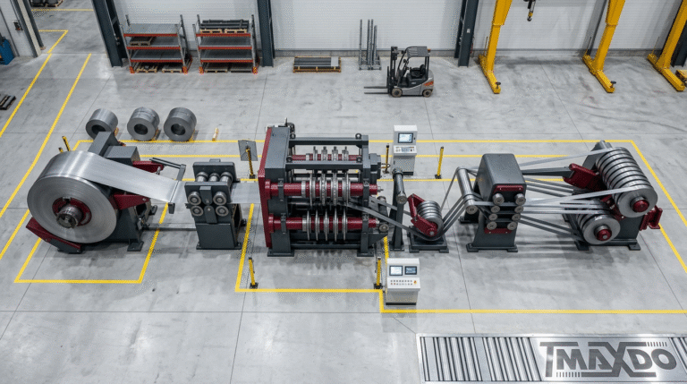
Slitting Line Engineering
Rotary knife assemblies execute continuous longitudinal cutting while preserving material in coiled form—the defining characteristic differentiating slitting from transverse cutting operations. Material passes through precisely positioned blade pairs at processing speeds determined by gauge thickness and quality requirements, with light-gauge operations achieving maximum line velocities.
MaxdoMachine’s MD-series demonstrates this capability across four production scales, each engineered for specific width envelopes and throughput requirements. The MD-850 accommodates coil widths from 20mm (specialized narrow-strip applications) to 820mm standard processing width, handling material gauges from 0.3mm ultra-thin sheet through 12mm plate thickness. The 138.5kW power system drives processing speeds reaching 250 m/min on light-gauge materials (0.3-3.0mm), with velocity automatically modulated for heavier gauges to maintain edge quality and dimensional accuracy. This thickness-speed correlation prevents the edge degradation that occurs when attempting maximum speeds on heavy-gauge stock.
Mid-range production environments benefit from the MD-1350 (300-1300mm width capacity, 318.5kW) or MD-1650 (300-1650mm, 422.5kW), while high-volume facilities processing wide coils select the MD-2200 offering 300-2150mm processing envelope with 422.5kW servo-controlled drive systems.
Critical slitting components include precision arbor systems enabling repeatable knife positioning to ±0.02mm, hydraulic or pneumatic tension control preventing material buckling during cutting cycles, scrap chopping assemblies managing edge trim disposal, and individual strip recoilers with independent tension regulation. Edge quality depends on blade sharpness (typically replaced after processing 400-500 tons of carbon steel), proper clearance between upper and lower knives (maintained at 5-8% of material thickness on MD-series equipment), and continuous material support through the cutting zone.
Strip width accuracy on modern servo-controlled slitting systems achieves ±0.1mm when processing materials within optimal gauge ranges, meeting ISO 2768 fine grade tolerances for subsequent manufacturing operations requiring dimensional consistency.
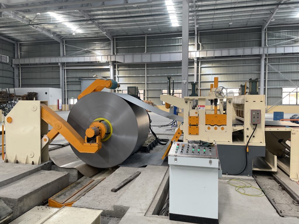
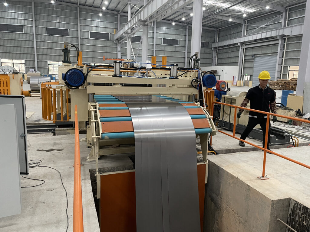
Cut-to-Length System Operations
CTL lines transform continuous coil into stacked flat sheets through integrated unwinding, leveling, measuring, shearing, and stacking sequences. The material pathway includes motorized uncoiling with mandrel expansion accommodating 508-762mm inner diameters, multi-roll leveling systems applying reverse-bend cycles that eliminate coil set curvature and internal stress patterns, servo-controlled roll feeding providing precise length measurement through encoder feedback, programmable shearing activated at designated positions, and automated stacking with sheet separation preventing surface contact damage.
Length precision derives from servo roll feeders advancing material in measured increments, synchronized with rotary or guillotine shear activation. High-performance installations achieve ±0.1mm length tolerance across sheets measuring multiple meters—essential for automated stamping where blank positioning directly affects formed part quality and die wear patterns. This tolerance level meets ISO 2768 fine grade requirements (±0.5mm for lengths up to 3000mm), with advanced systems exceeding standard specifications.
Leveling capability distinguishes CTL equipment from simple cut-off machines. Multi-roll levelers remove both coil set (curvature imparted during coiling) and internal stress patterns that would otherwise cause blanks to warp after cutting, particularly problematic in stamping operations where press feeding systems require flat stock. The leveling intensity adjusts based on material yield strength and thickness, with heavier gauges requiring increased roller pressure and additional bending stations.
Material-Specific Processing Parameters
| Material Category | Thickness Range | Slitting Line Performance | CTL Line Performance | Optimal Technology Selection |
|---|---|---|---|---|
| Cold-rolled steel | 0.3-1.5mm | Excellent for tube manufacturing, continuous forming operations; minimal handling reduces coating damage risk | Excellent for precision stamping blanks, appliance panels requiring flatness <0.3mm/m | Output format requirements determine selection—coiled strips for continuous processes, flat blanks for discrete operations |
| Stainless steel (304/316) | 0.5-3.0mm | Ideal for architectural trim strips, kitchen equipment components; work-hardening characteristics require specialized blade metallurgy | Required for elevator panels, commercial equipment enclosures where surface finish and dimensional precision are critical | CTL preferred when flatness specifications exceed ±0.5mm/m; slitting for continuous-feed applications accepting minimal coil set |
| Aluminum alloy (3003/5052) | 0.8-6.0mm | Efficient for extrusion feeder strips, cladding material; lower yield strength demands adjusted tension control strategies | Necessary for formed refrigerator components, HVAC housings; aluminum’s spring-back characteristics require enhanced leveling capacity | CTL lines handle aluminum forming blanks effectively; slitting serves continuous aluminum processing with proper tension management |
| High-strength steel (≥350MPa) | 2.0-12mm | Possible with heavy-duty MD-1650/MD-2200 platforms; increased cutting forces reduce blade life 40-60% vs. mild steel | Preferred for structural components, automotive chassis blanks; enhanced leveling systems manage higher yield strength materials | CTL technology better suited for heavy-gauge high-strength applications; slitting viable for lighter gauges with blade life considerations |
| Galvanized/pre-coated | 0.4-2.5mm | Excellent choice; continuous coiled format minimizes handling-related coating damage; edge quality preserves coating integrity | Good performance with proper leveler configuration preventing coating fracture; requires specialized hold-down systems | Slitting reduces coating damage from repeated handling; CTL acceptable when leveling parameters optimized for coated materials |
MaxdoMachine’s MD-series accommodates four standardized thickness categories: 0.3-3.0mm (light-gauge sheet and strip products for HVAC, appliances, electronics enclosures), 1.5-6.0mm (light-medium applications including automotive formed parts and architectural panels), 2.0-8.0mm (medium-gauge structural components, equipment bases, industrial fabrications), and 4.0-12mm (heavy plate for structural steel applications, machinery bases, shipbuilding components). This modular gauge approach enables single equipment platforms to serve multiple product lines, reducing capital equipment requirements compared to dedicated light and heavy-gauge installations.
Application-Driven Technology Selection
Slitting Line Optimization Scenarios
Tube and pipe manufacturing represents the primary slitting application domain globally. Consider a manufacturer producing HVAC spiral ductwork from 0.8mm galvanized steel, receiving 1250mm-wide master coils from steel mills. Production requirements include 127mm, 152mm, and 203mm strip widths for different duct diameter specifications. An MD-1350 slitting installation divides each master coil into nine 127mm strips (with 107mm total edge trim), delivering material in the coiled format the spiral tube mill requires while eliminating intermediate handling steps that risk coating damage. The alternative—CTL processing followed by re-coiling—adds equipment cost, processing time, and quality degradation without operational benefit.
Roll forming operations demonstrate similar slitting advantages. Steel building manufacturers forming C-purlins, Z-purlins, and roof panel profiles process continuous coiled strip through multiple sequential forming stations. Slitting the incoming coil once provides weeks of production material in the optimal format, whereas CTL processing would generate thousands of individual sheets requiring separate feeding mechanisms, accumulation systems, and additional handling labor.
Precision strip products including transformer laminations, industrial saw blades, and engineered springs emerge most efficiently from slitting lines because dimensional accuracy concentrates on width control rather than length management. Operations requiring multiple widths from common stock material achieve maximum raw material yield through slitting, as longitudinal edge trim represents the only scrap generation point—typically 2-4% material loss compared to 5-12% common in CTL operations optimized for width rather than minimizing trim.
CTL Line Essential Applications
Stamping and forming operations producing discrete components cannot utilize coiled strip input unless intermediate uncoiling and feeding equipment is installed—negating the slitting efficiency advantage. An automotive tier-one supplier producing body reinforcement brackets receives 1.5mm cold-rolled steel in 1500mm-wide coils and must deliver 450mm × 650mm blanks to servo press lines operating at 15 strokes per minute. The CTL system uncoils material, applies multi-roll leveling removing coil set that would cause press feeding misalignment and die wear, and shears to length with ±0.2mm tolerance. Blanks stack automatically for forklift transport to press stations, with stack counts matching press magazine capacity. The flatness achieved through proper leveling (typically 0.2-0.4mm deviation across 650mm length) prevents press feeding errors that damage expensive progressive dies.
Appliance manufacturing exemplifies CTL technology requirements. Refrigerator door production demands precisely dimensioned blanks undergoing forming, welding, and painting operations before final assembly. A major North American appliance manufacturer implemented a CTL line with integrated punching capability delivering 820mm × 1650mm door blanks with pre-punched hinge mounting holes positioned to ±0.15mm tolerance. This integrated approach eliminated two separate operations (CTL blanking followed by CNC punching) while maintaining dimensional control critical for assembly fit and paint line compatibility. The installation reduced door panel cost per unit by 23% while improving first-pass quality metrics from 94% to 99.2%.
Architectural panel fabrication for elevator cabs, building facades, and equipment enclosures specifies CTL processing because subsequent fabrication shops require flat sheets for cutting, forming, welding, and finishing operations. A 3.0mm stainless steel coil processed through a CTL line with proper leveling emerges as stacked sheets exhibiting flatness suitable for brake forming or laser cutting without intermediate flattening—a critical quality attribute. Attempting to use slit coils would require subsequent flattening operations degrading edge quality, introducing additional handling damage risk, and consuming processing time without value creation.
Production Volume Economic Analysis
Linear Throughput Comparison
Slitting lines demonstrate superior processing velocity when measured in linear meters per hour—the fundamental throughput metric for continuous operations. An MD-1650 operating at 200 m/min sustained speed (accounting for knife changeovers and coil threading sequences) processes 12,000 linear meters during a single eight-hour shift, equivalent to sixty master coils at 200 meters each. This material volume converted to 2.5-meter blanks represents 4,800 individual sheets—a CTL line output requiring significantly longer cycle time due to acceleration-deceleration sequences for each shear actuation.
CTL productivity depends heavily on blank length, with shorter blanks enabling higher stroke frequencies. A high-performance CTL installation produces 100 strokes per minute processing 600mm-length blanks (60 linear meters/minute effective throughput) but achieves only 30 strokes per minute at 3000mm blank length (90 linear meters/minute) due to material acceleration limitations and shear cycle time. The throughput crossover point where CTL lines match slitting velocity occurs when downstream operations specifically require discrete blanks—attempting to produce blanks by first slitting then subsequently cross-cutting adds handling complexity and quality degradation without economic benefit.
Facility Space Utilization
Slitting line footprints scale proportionally with maximum coil width and weight handling capacity. A complete MD-1350 installation (1300mm width capacity processing 35-ton coils) typically occupies 18-22 meters floor length including uncoiler, slitter head, scrap winder, and multiple recoiler stations, with 4-5 meters width requirement. The equipment arrangement follows predominantly linear configuration, simplifying integration into existing facility layouts without complex material flow routing.
CTL lines require additional floor allocation for sheet stacking and handling equipment. A comparable width-capacity CTL system extends 20-25 meters in length with 6-8 meters width accommodating the leveler (requiring more roll stations than slitting entry equipment), shear mechanism, and sheet stacking/separation systems with adequate operator access. Material flow characteristics differ significantly: slitting lines deliver output as multiple coils requiring forklift transport to next operation, while CTL systems produce stacked sheets on pallets or in bundles with integrated strapping equipment preparing material for shipment or storage.
Overhead clearance requirements merit consideration in facilities with height constraints. Slitting line uncoilers and recoilers handling 35-ton coils at 1600mm outer diameter require minimum 4-5 meter ceiling height, while CTL systems processing similar material dimensions need 4.5-5.5 meters accounting for leveler clearances and sheet stacking mechanisms.
Changeover Flexibility and Product Mix Adaptation
Slitting Line Setup Procedures
Slitting operations accommodate product variation through knife position adjustment on precision arbor systems. MD-series equipment employs quick-change arbor designs where knife repositioning for different strip width patterns requires 15-30 minutes for experienced operators processing common material thickness. The procedure involves loosening arbor clamps, sliding knife assemblies to new positions per setup sheet specifications, verifying positions with precision measuring tools, and re-torquing clamp hardware to specified values. Modern installations incorporating servo-positioned knives reduce this duration to 8-12 minutes through automated positioning sequences.
Transitioning between material gauge categories (light to medium or medium to heavy) involves more substantial setup including knife selection based on thickness (heavier gauges require thicker blades and increased side support), side guide adjustment to accommodate different coil widths, and tension system recalibration matching material yield strength. This thickness-driven changeover typically consumes 45-90 minutes depending on the magnitude of gauge variation and operator proficiency levels. Facilities processing diverse gauge ranges benefit from dedicated knife sets pre-assembled on spare arbors, enabling arbor exchange in 30-40 minutes compared to individual knife repositioning.
CTL Line Adjustment Protocols
CTL changeovers primarily involve length setting modifications in the control system—software parameter adjustments requiring under five minutes when material thickness and width remain constant. The operator enters new length specifications, adjusts shear timing parameters if blank length variation exceeds 500mm, and modifies stacking count parameters matching customer bundle requirements. This rapid changeover capability makes CTL technology advantageous for operations serving diverse customer specifications with frequent order transitions.
Material thickness changes necessitate leveler adjustment applying appropriate bending cycles for the new gauge. Leveler setup involves calculating required roll penetration depth based on material yield strength and thickness, adjusting entry and exit roll positions, and verifying flatness on trial pieces. This mechanical setup requires 20-40 minutes depending on thickness variation magnitude and whether servo-controlled or manual adjustment systems are installed. Advanced installations with automatic leveler setup reduce this to 10-15 minutes through pre-programmed material profiles stored in the control system.
Width changes on CTL equipment are less common in optimized operations, as most facilities specify coil width matching required blank width (or slight oversize allowing edge trimming). When width transitions occur, side guide repositioning follows procedures similar to slitting operations, requiring 15-25 minutes for manual systems or 5-8 minutes with servo-positioned guides.
Operations serving diverse customer requirements with frequent specification changes favor CTL lines for their rapid length adjustment capability, while facilities producing standardized strip widths in extended production runs benefit from slitting’s continuous operation eliminating frequent changeovers.
Combined Processing Strategies
Multi-blanking systems represent hybrid technology combining slitting’s width division with CTL’s transverse cutting, producing multiple blanks across coil width in single-pass processing. This approach suits operations producing moderate quantities of various blank sizes, as the system slits material to required widths then simultaneously cross-cuts all strips to specified length before separation and stacking. A refrigerator manufacturer requiring 400mm, 450mm, and 500mm wide door blanks at 1800mm length configures a multi-blanking line to slit the 1350mm master coil into three strips (with edge trim) and shear all three simultaneously at 1800mm intervals, tripling output compared to processing each width through sequential CTL operations.
MaxdoMachine’s application engineering evaluates combined system implementations when customer product matrices involve 5-15 distinct blank sizes across multiple widths, representing the economic crossover between dedicated CTL processing and multi-blanking efficiency. Learn more about multi-blanking advantages for complex product portfolios.
Equipment Specification Framework
Initial Assessment Criteria
What output format does your downstream equipment require? Operations utilizing coiled strip input for tube mills, roll forming lines, or continuous processing equipment should specify slitting technology. Facilities producing discrete parts through stamping, forming, or fabrication operations require CTL systems delivering flat blank stock. This fundamental question eliminates approximately 60% of evaluation complexity by aligning technology selection with downstream process requirements.
What production volumes characterize your typical manufacturing runs? High-volume production of standardized dimensions (measured in tens of thousands of linear meters per specification) favors slitting’s continuous throughput advantage. Operations characterized by frequent changeovers serving diverse customer orders benefit from CTL’s rapid length-setting flexibility. The economic crossover typically occurs around 8,000-12,000 linear meters per specification, below which CTL changeover flexibility provides value exceeding slitting’s throughput advantage.
What material thickness range defines your product portfolio? Light to medium gauge operations (0.3-6.0mm) achieve excellent results from either technology, with selection driven by output format and volume considerations previously discussed. Heavy gauge applications exceeding 6.0mm thickness increasingly favor CTL processing, as leveling capability becomes critical for achieving flatness specifications and slitting knife life decreases substantially with material thickness. The MD-850’s ability to process up to 12mm thickness demonstrates slitting viability in medium-heavy applications, though blade replacement frequency increases 40-60% compared to light-gauge processing.
What width dimensions do your products require? Applications utilizing full master coil width (or requiring only minimal edge trimming) are CTL candidates, as slitting provides no width division benefit while adding unnecessary processing complexity. Operations requiring multiple narrow widths from wider stock material indicate slitting technology, maximizing raw material yield by eliminating the width-related scrap common in CTL operations. A simple calculation: if your product widths sum to less than 85% of available coil width, significant material waste will occur in CTL processing—slitting becomes the economically preferred option.
What quality specifications govern your products? Requirements emphasizing length tolerance, flatness, and burr-free sheared edges indicate CTL processing with precision leveling and maintained shear blade condition. Specifications prioritizing longitudinal edge quality, consistent strip width, and minimal width variation favor slitting systems with properly maintained knives. Understanding these quality drivers clarifies which technology delivers your required attributes most effectively.
Safety and Regulatory Compliance
Modern coil processing equipment must comply with international safety frameworks protecting operators from mechanical hazards inherent in high-speed material handling and cutting operations. MaxdoMachine’s MD and CT series incorporate safety features meeting ISO 13849-1 requirements for control system reliability and Machinery Directive 2006/42/EC provisions for European Union installations.
Critical safety implementations include emergency stop systems with redundant logic circuits positioned at strategic operator stations and material entry/exit points, enabling immediate equipment shutdown in emergency conditions. Light curtains and physical guarding meet OSHA 1910.212 requirements for protecting operators from in-running nip points at uncoilers, leveler roll stations, and recoiler positions. These safeguards automatically halt equipment motion when photoelectric beams are interrupted, preventing operator contact with moving components.
Coil tension release controls represent particularly important safety features, as sudden material spring-back during threading operations has resulted in serious operator injuries in facilities lacking proper safeguards. Controlled tension release mechanisms prevent the violent coil unwinding that occurs when improperly managed, a hazard documented in multiple workplace safety incident reports.
Lockout/tagout provisions enable maintenance personnel to safely access knife assemblies, shear mechanisms, and drive systems for adjustment and service procedures. Proper implementation of lockout procedures has proven critical in preventing equipment startup during maintenance activities—a leading cause of serious manufacturing injuries.
Dimensional accuracy verification on MaxdoMachine equipment follows ISO 2768 general tolerance standards, with specific quality grade agreements (fine, medium, coarse) established during equipment specification discussions based on end-product requirements.
MaxdoMachine Equipment Portfolio Comparison
| Equipment Platform | Technology Type | Width Capacity | Thickness Range | Power System | Typical Applications | Distinguishing Advantage |
|---|---|---|---|---|---|---|
| MD-850 | Slitting | 20-820mm | 0.3-12mm | 138.5 kW | HVAC ducting strips, narrow specialty widths, appliance component strips | Compact footprint with exceptional width range flexibility; processes narrow strips uneconomical on larger equipment |
| MD-1350 | Slitting | 300-1300mm | 0.3-12mm | 318.5 kW | General fabrication strips, roll forming feedstock, tube mill material | Mid-range versatility balancing capacity and facility space requirements |
| MD-1650 | Slitting | 300-1650mm | 0.3-12mm | 422.5 kW | Wide coil division, multiple simultaneous strip outputs, high-volume production | High-capacity strip production with enhanced servo control systems |
| MD-2200 | Slitting | 300-2150mm | 0.3-12mm | 422.5 kW | Maximum-width applications, heavy-duty processing, structural component strips | Largest available coil processing envelope in MD series |
CT-series cut-to-length equipment specifications are configured based on specific application requirements and production volume targets
The MD-850’s exceptional capability processing widths from 20mm establishes it as the preferred platform for operations requiring narrow specialty strips alongside standard production widths—eliminating the need for dedicated narrow-width equipment. This flexibility proves particularly valuable in HVAC manufacturing and appliance production where product portfolios span diverse width specifications. For detailed processing parameters and application examples, visit the MD-850 product specification page.
Frequently Asked Questions: Technology Selection
Q: Can the same equipment process both steel and aluminum materials?
A: Yes, both slitting and CTL lines handle multiple material types within their designed thickness ranges. Material transitions require tension control and leveling parameter adjustments (30-60 minutes for slitting systems, 20-40 minutes for CTL equipment) but involve no fundamental equipment reconfiguration. Aluminum processing demands lower tension settings and adjusted leveling intensity compared to steel due to differing yield strength and surface hardness characteristics.
Q: What dimensional accuracy can I expect from slitting operations?
A: High-precision slitting systems with properly maintained blade assemblies and servo-controlled knife positioning achieve ±0.1mm width tolerance on light to medium gauge materials, meeting ISO 2768 fine grade dimensional requirements. This accuracy level suits downstream operations including roll forming, tube production, and precision strip applications. Heavier gauges and work-hardening materials like stainless steel may exhibit ±0.15mm variation due to spring-back characteristics.
Q: How much facility space should I allocate for coil processing equipment?
A: Slitting lines require 18-25 meters length × 4-6 meters width depending on maximum coil weight capacity and number of recoiler positions. CTL systems need 20-28 meters length × 6-8 meters width including leveling equipment and sheet stacking mechanisms. Both technologies require 4-5 meter minimum ceiling height for handling large-diameter coils. Detailed facility layout planning should account for material staging areas, maintenance access zones, and electrical infrastructure locations.
Q: What return on investment timeline is realistic for coil processing equipment?
A: Operations processing 500+ tons monthly through owned equipment typically achieve 18-30 month ROI through eliminating outsourced slitting/blanking service costs, reducing material waste 3-7%, and decreasing labor requirements compared to manual processing methods. Specific ROI calculations depend on current processing costs, anticipated production volumes, and material types processed. Facilities currently paying $0.15-0.25 per linear meter for outsourced processing realize particularly rapid payback periods.
Q: What electrical infrastructure does MD-series equipment require?
A: MD-series platforms require three-phase electrical service ranging from 138kW (MD-850) to 422kW (MD-1650/MD-2200) depending on model selection. Electrical planning must accommodate startup surge current typically 1.5-2× running current during motor acceleration. Most industrial facilities possess adequate electrical capacity, though dedicated circuits and proper conductor sizing ensure reliable operation. Consult facility electrical engineers early in the planning process to identify any required infrastructure upgrades.
Q: How does material thickness affect processing speed?
A: Processing velocity decreases as material thickness increases due to greater cutting forces, increased leveling requirements, and material handling constraints. The MD-series achieves maximum speeds of 250 m/min processing 0.3-3.0mm light-gauge materials, with automatic velocity reduction to 120-180 m/min for 4-8mm medium gauge, and further reduction to 60-100 m/min for 8-12mm heavy plate. This thickness-speed correlation maintains edge quality and dimensional accuracy that would degrade at inappropriate processing speeds.
Partnering With Application Engineering Specialists
Selecting coil processing technology based solely on equipment specifications overlooks critical variables including material behavior characteristics, downstream process integration requirements, facility infrastructure constraints, and long-term production evolution planning. MaxdoMachine’s application engineering team brings three decades of specialization in slitting, CTL, and multi-blanking systems development—knowledge applied to optimizing these variables for specific manufacturing environments.
Engineering consultation examines actual coil characteristics beyond nominal specifications (yield strength variations affecting leveling requirements, surface finish restrictions influencing material handling methods, coil set severity determining leveling intensity needs), reviews downstream equipment capabilities and limitations (press feeding systems, tube mill mandrel ranges, roll forming station spacing), analyzes production data identifying volume patterns and specification clustering revealing optimal equipment configuration, and develops equipment specifications matching actual operational requirements rather than theoretical maximum capabilities.
The MD-series platform approach—standardized equipment modules scaled from 820mm to 2150mm width capacity, accommodating 0.3-12mm thickness across common gauge categories—enables specification refinement without custom engineering delays extending project timelines. This modular methodology reduces implementation risk while maintaining capability for future production expansion or product line additions as market demands evolve.
Next Steps: Process Review Consultation
Translating the technical distinctions between CTL and slitting technologies into optimal equipment specifications for your operation requires detailed examination of material characteristics, production volumes, quality requirements, and facility constraints specific to your manufacturing environment. MaxdoMachine’s application engineers conduct complimentary 30-minute process reviews evaluating your current coil processing approach, identifying efficiency improvement opportunities, and recommending equipment configurations aligned with production and business objectives.
Schedule your free consultation to discuss:
- Material gauges, widths, and types you process
- Typical production volumes and order pattern characteristics
- Downstream equipment and processes requiring coil-processed input
- Quality specifications and dimensional tolerance requirements
- Facility layout constraints affecting equipment installation
- Future production expansion or product line development plans
This focused technical discussion clarifies whether slitting lines, CTL systems, multi-blanking platforms, or hybrid configurations deliver optimal performance for your specific applications.
Contact MaxdoMachine’s engineering team to arrange your consultation and receive detailed technical documentation on MD-series capabilities matched to your material specifications and production requirements.
MaxdoMachine: 20+ years engineering precision coil processing solutions for manufacturers worldwide. Delivering advanced slitting, CTL, and multi-blanking technology with comprehensive application support from specification through installation and ongoing optimization.