Complete Guide to Servo Roll Feed Controllers for Coil Processing Lines
Expert guide to servo roll feed controllers: selection criteria, integration methods, technical specs, and ROI optimization for metal coil processing lines.
Servo roll feed controllers have transformed metal coil processing operations by delivering precision that mechanical and hydraulic systems simply cannot match. In modern fabrication facilities, these controllers achieve feeding accuracy within ±0.02mm to ±0.1mm, enabling manufacturers to reduce material waste by up to 4% while increasing throughput. For production managers evaluating roll feed equipment upgrades, understanding the technical specifications, integration requirements, and return on investment of servo-driven systems is essential to making informed capital equipment decisions.
Understanding Servo Roll Feed Controllers in Modern Coil Processing
Servo roll feed controllers are computerized feeding systems that use closed-loop feedback mechanisms to precisely control the advancement of metal coil material through processing lines. Unlike traditional mechanical cam-driven or pneumatic feeders, servo systems employ brushless servo motors with high-precision encoders that continuously monitor and adjust feed position in real-time.
The evolution from mechanical to servo-driven systems represents a fundamental shift in coil processing capabilities. Traditional mechanical feeders rely on fixed cam profiles that limit flexibility and typically achieve accuracy of ±0.5mm at best. Servo controllers, by contrast, use programmable digital controls that allow operators to adjust feed length from 0.1mm to 9999.99mm with sub-0.1mm repeatability.
Key advantages over hydraulic and pneumatic systems include significantly faster response times, elimination of hydraulic fluid maintenance requirements, reduced energy consumption, and the ability to synchronize precisely with downstream stamping or cutting operations. The closed-loop feedback system continuously compares commanded position against actual encoder feedback, making micro-adjustments hundreds of times per second to maintain accuracy even as material properties vary.
For precision-critical applications, servo roll feed controllers achieve the ±0.1mm accuracy required for automotive stamping, appliance manufacturing, and aerospace components. This level of precision directly translates to reduced scrap rates, fewer rejected parts, and the ability to meet tighter customer specifications—advantages that mechanical systems cannot deliver consistently.
Technical Specifications and Performance Parameters
Understanding critical performance specifications is essential when evaluating roll feed equipment for your coil processing line. The most important technical parameters include feed length accuracy, maximum feed speed, material thickness capacity, and motor torque capabilities.
Feed length accuracy represents the deviation between programmed and actual material advancement. Precision-grade servo controllers achieve ±0.02mm accuracy with positioning pins in dies, while standard systems typically deliver ±0.1mm accuracy. This specification directly impacts part quality, with tighter tolerances enabling more complex stamping operations and reducing downstream rework.
Material handling specifications vary significantly across controller models:
- Thickness capacity: Entry-level systems handle 0.1-1.6mm materials, while heavy-duty controllers process up to 4.5mm thick coils
- Feed speed: Standard systems operate at 20 m/min, with high-speed variants reaching 192 m/min (630 FPM)
- Maximum feed length: Most controllers support programmable lengths up to 9999.99mm in a single feed cycle
- Material width: Controllers are available for coil widths from 100mm to over 1350mm
Servo motor torque requirements scale with material weight and thickness. A 400W servo motor suffices for light-gauge materials under 1mm thick, while medium-gauge applications (0.3-3.5mm) typically require 750W to 1.5kW motors. Heavy coils demand higher torque capacity to maintain acceleration and deceleration performance without motor overload conditions.
Control system architecture significantly impacts integration capabilities. Modern servo feeders feature PLC-based control systems from manufacturers like Mitsubishi, Siemens, and ABB, with support for multiple communication protocols including Modbus TCP, PROFINET, and EtherNet/IP. High-sensitivity decoders with resolutions of 0.01mm or finer provide the feedback precision necessary for accurate positioning.
| Controller Grade | Accuracy | Feed Speed | Thickness Range | Typical Application |
|---|---|---|---|---|
| Standard | ±0.1mm | 20 m/min | 0.2-3.5mm | General stamping, brackets |
| Precision | ±0.03mm | 30 m/min | 0.1-2.0mm | Electronics, connectors |
| High-Speed | ±0.05mm | 192 m/min | 0.1-1.6mm | Motor laminations |
| Heavy-Duty | ±0.1mm | 15 m/min | 1.0-4.5mm | Appliances, structural parts |
Real-time monitoring capabilities enable predictive maintenance and process optimization. Advanced controllers log feed counts, alarm histories, and performance metrics accessible through HMI touchscreens, allowing production managers to identify developing issues before they cause unplanned downtime.
How Servo Controllers Integrate with Complete Coil Processing Lines
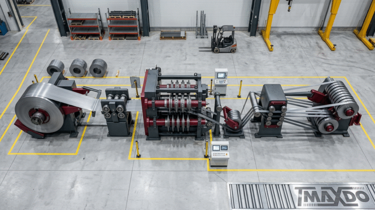
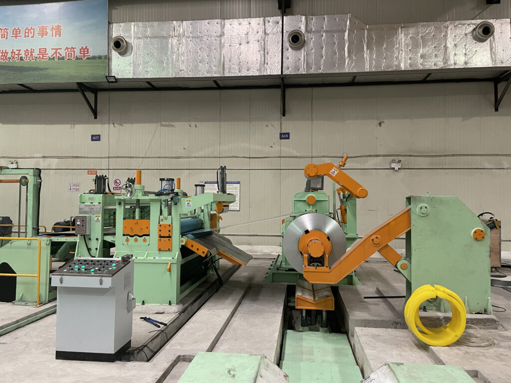
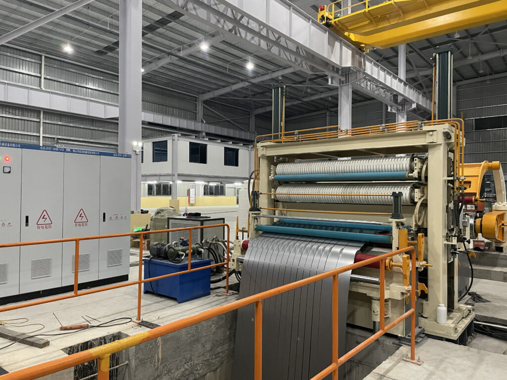
Servo roll feed controllers function as the precision timing hub within integrated coil processing system equipment installations. Proper integration with upstream decoilers, straighteners, and downstream blanking or stamping equipment is essential for achieving system-level performance targets.
Integration with decoilers and straighteners requires careful synchronization to maintain consistent material tension without causing coil breaks or surface defects. Servo feeders communicate with motorized decoilers through PLC networks, automatically adjusting uncoiling speed to match feed demand. When material is fed forward, the decoiler releases additional coil; when feeding pauses, the decoiler stops rotation to prevent slack accumulation.
Straightener integration presents particular challenges for precision applications. Material that exits the straightener with residual camber or coil set will affect feed accuracy regardless of servo controller precision. Modern installations incorporate feedback from the servo feeder to the straightener’s adjustment mechanism, creating a closed-loop system that automatically optimizes straightening pressure based on actual feed accuracy measurements.
Synchronization with downstream cutting or punching operations determines overall line productivity. Servo feeders receive trigger signals from press controllers that initiate the feed cycle as the ram returns to top dead center. Communication protocols like EtherNet/IP enable deterministic timing with latencies under 1 millisecond, ensuring the material reaches the correct position before the next stamping cycle begins.
Material handling workflow optimization requires consideration of the entire process sequence. For cut-to-length operations, the servo feeder must coordinate with precision cutting systems to ensure consistent blank lengths regardless of line speed variations. This coordination prevents the accumulation of tolerance stack-up that occurs when each component operates independently.
Communication protocols between servo controllers and line components utilize industrial Ethernet standards. Modbus TCP provides a reliable, widely-supported protocol for basic data exchange between PLCs and servo drives. PROFINET offers faster cycle times and more sophisticated diagnostics for complex installations. EtherNet/IP delivers the real-time performance required for high-speed stamping lines operating above 400 strokes per minute.
MaxDo’s MD series installations demonstrate the performance potential of properly integrated systems. By coordinating servo feed controllers with precision straighteners and optimized decoilers, these installations achieve 96%+ material yield—representing a 4-6% improvement over conventional mechanical feed systems. This yield improvement alone typically recovers equipment investment within 12-18 months for high-volume operations processing premium materials like stainless steel or aluminum alloys.
Selection Criteria for Roll Feed Controllers
Selecting appropriate roll feed equipment requires systematic evaluation of material specifications, production requirements, and integration compatibility. Making the wrong choice leads to either over-investment in unnecessary capability or underperformance that limits production quality and throughput.
Material specifications form the foundation of selection criteria. Document the full range of materials your operation processes:
- Thickness range (minimum to maximum)
- Material width (coil width specifications)
- Tensile strength and hardness values
- Surface finish requirements (mill finish, pre-painted, polished)
- Coil weight and inside diameter
Controllers must accommodate your thickest, hardest materials while maintaining accuracy with thin, delicate stock. A system specified for 0.2-3.5mm thickness cannot reliably process 4.0mm material without motor overload conditions and reduced accuracy.
Production requirements determine necessary speed and precision capabilities. Calculate:
- Required parts per hour at each product in your mix
- Feed lengths for typical and extreme parts
- Acceptable tolerance range for your most demanding applications
- Batch sizes and changeover frequency
- Expected equipment utilization (shifts per day, days per week)
High-mix environments with frequent changeovers benefit from servo feeders with recipe storage that recalls optimal settings for each part number. Dedicated high-volume lines may justify investment in high-speed controllers that reduce cycle time and increase capacity.
Compatibility with existing equipment often constrains selection options. Audit your current installation:
- Press or stamping equipment specifications and control systems
- Available floor space and mounting configurations
- Electrical service capacity (voltage, phase, available amperage)
- PLC brand and communication protocol support
- Decoiler and straightener control capabilities
Retrofitting servo feeders into legacy lines may require control system upgrades to enable proper communication and synchronization. Budget for these ancillary costs during the selection process.
Budget considerations extend beyond initial purchase price. Calculate total cost of ownership including:
- Equipment purchase price and delivery
- Installation labor and commissioning
- Training for operators and maintenance personnel
- Annual maintenance costs and spare parts inventory
- Expected material yield improvement value
- Productivity increase from faster changeovers
ROI analysis typically shows payback periods of 6-18 months for servo feeder installations, with faster returns in operations processing expensive materials or running high-mix production.
Vendor evaluation should verify manufacturing quality and support capabilities. Prioritize suppliers offering:
- ISO 9001 certification demonstrating quality management systems
- Documented installation base in your industry vertical
- Local service and technical support availability
- Comprehensive operator training programs
- Spare parts availability with reasonable lead times
- Control system compatibility with your existing equipment
Companies like MaxDo, with over 20 years of R&D experience and 500+ installations across 30+ countries, provide the proven track record necessary for mission-critical production equipment decisions.
Installation and Commissioning Best Practices
Proper installation and commissioning procedures are essential for achieving specified performance from servo roll feed controllers. Even premium equipment will underperform if installation shortcuts compromise mechanical alignment or electrical integration.
Pre-installation site preparation begins weeks before equipment arrival. Verify that foundation requirements meet manufacturer specifications, typically including a level concrete floor with sufficient load-bearing capacity. Electrical service must provide clean power at the specified voltage and phase configuration, with adequate amperage capacity for the servo motor and control system. Many installations benefit from dedicated circuit breakers and isolation transformers to protect sensitive servo drives from voltage spikes and electrical noise.
Compressed air supply is required for pneumatic release mechanisms common on medium and heavy-duty feeders. Ensure air pressure meets specifications (typically 6-8 bar) with adequate flow capacity and filtration to prevent contamination of pneumatic valves.
Mechanical alignment and calibration procedures directly impact feed accuracy. Mount the servo feeder on a rigid base that prevents deflection under operating loads. Misalignment between feeder mounting and the press bed or die mounting surface translates to angular errors that accumulate with feed length.
Feed roll alignment requires precision measurement equipment. Upper and lower rolls must be parallel within 0.02mm across the full material width. Check parallelism using precision ground gauge blocks or dial indicators at multiple width positions. Misalignment causes uneven grip pressure that leads to material skewing and reduced accuracy.
Roll gap adjustment must accommodate your material thickness range without excessive compression that deforms the material or insufficient grip that allows slippage. Most controllers specify roll pressure settings based on material thickness and hardness. Start with manufacturer recommendations and fine-tune based on observed performance.
Electrical integration and safety protocols require attention to both power distribution and control signal wiring. Servo drives generate electrical noise that can interfere with control signals if proper grounding practices are not followed. Use shielded cables for all encoder feedback wiring and maintain separation between power cables and signal cables.
PLC integration involves configuring communication parameters to match your control system. Set the correct protocol (Modbus, PROFINET, EtherNet/IP), IP addresses, and baud rates. Verify bi-directional communication by monitoring data exchange between the servo controller and press PLC before running production.
Emergency stop circuits must integrate with line-level safety systems to ensure that activating any e-stop button along the processing line immediately halts feeder motion. Test all safety interlocks before running material through the system.
Testing and validation procedures verify that the installed system meets accuracy specifications. The standard procedure involves:
- Load test material matching production specifications
- Program feed lengths spanning your typical range (minimum, typical, maximum)
- Execute 50-100 feed cycles at each length setting
- Measure actual material advancement using precision gauges
- Calculate deviation from programmed length
- Adjust controller parameters if deviations exceed specifications
Document baseline performance metrics including accuracy at various feed lengths and speeds. This data provides reference points for future troubleshooting and preventive maintenance decisions.
Common installation pitfalls that compromise performance include:
- Inadequate foundation rigidity causing vibration
- Misaligned mounting relative to press or die
- Insufficient roll pressure adjustment range
- Contaminated or worn feed rolls during initial setup
- Improper servo gain settings causing oscillation
- Communication protocol mismatches preventing synchronization
Working with experienced installation technicians familiar with your specific equipment model minimizes these risks and accelerates commissioning.
Optimizing ROI Through Advanced Controller Features
Material waste reduction capabilities directly impact operating costs for facilities processing expensive alloys or pre-finished materials. Servo roll feed controllers minimize waste through multiple mechanisms. Precision feeding reduces the scrap typically generated during setup and first-piece qualification, with servo systems achieving stable production within 5-10 pieces compared to 20-50 pieces for mechanical feeders.
End-of-coil management features maximize material utilization by enabling production closer to the coil tail. Advanced controllers detect when remaining coil length is insufficient for the programmed feed and automatically alert operators or switch to a backup coil, preventing the 2-3 meters of waste common when coils run out unexpectedly.
Energy efficiency gains compared to traditional systems accumulate significantly over multi-shift operations. Servo motors consume power proportional to load, drawing minimal current during idle periods between feed cycles. Pneumatic and hydraulic feeders continuously consume energy maintaining system pressure regardless of actual demand. For a typical 3-shift operation, servo feeders reduce annual energy consumption by 4,000-8,000 kWh compared to hydraulic alternatives.
Regenerative braking capabilities allow servo drives to return energy to the electrical supply during deceleration, further improving efficiency. This feature provides the greatest benefit in high-speed applications with rapid acceleration and deceleration cycles.
Reduced setup time and faster changeovers improve effective equipment utilization. Recipe storage systems allow operators to recall optimal settings for each part number with a single button press rather than manually adjusting multiple parameters. Typical changeover time reduces from 15-30 minutes for mechanical feeders to under 5 minutes for recipe-driven servo systems.
Quick-change tooling compatibility enables even faster transitions between similar part families. Some installations achieve changeovers in under 2 minutes by combining servo feeder recipes with modular die systems and automated die height adjustment.
Predictive maintenance features minimize unplanned downtime by identifying developing problems before they cause equipment failure. Modern controllers monitor parameters including motor current draw, servo drive temperature, encoder signal quality, and feed accuracy trends. When values drift outside normal operating ranges, the system generates alerts prompting preventive maintenance.
Data logging capabilities enable analysis of long-term performance trends. Production managers can identify patterns like gradual accuracy degradation suggesting feed roll wear or increasing motor current indicating lubrication needs. Addressing these issues during scheduled maintenance windows prevents mid-shift breakdowns that disrupt production schedules.
Calculating payback period requires analysis of specific operational improvements. The standard ROI calculation considers:
Annual savings = Material waste reduction value + Labor savings + Energy savings + Scrap reduction value
For example, a facility processing 1,000 tons annually of stainless steel coil at $2,500/ton with a servo feeder reducing waste from 5% to 1%:
- Material waste reduction: 40 tons × $2,500 = $100,000
- Labor savings from faster changeovers: 2 hours/day × $60/hour × 250 days = $30,000
- Energy savings: 6,000 kWh × $0.12/kWh = $720
- Reduced scrap from improved accuracy: $15,000
Total annual savings: $145,720
With a typical servo feeder investment of $50,000-80,000 including installation, the payback period ranges from 6-12 months. Operations processing more expensive materials or running higher volumes achieve even faster returns.
Troubleshooting Common Servo Feed Controller Issues
Feed length accuracy problems represent the most frequent performance complaint for servo roll feed controllers. When actual material advancement deviates from programmed length, systematically check material thickness settings first. Controllers calculate feed based on roller circumference and material thickness—entering incorrect thickness values causes proportional feed errors.
Inspect feed rolls for wear, contamination, or damage. Worn knurling patterns reduce grip effectiveness, allowing material to slip between rolls rather than advancing the commanded distance. Oil, coolant residue, or metal particles on roll surfaces similarly compromise traction. Clean rolls with appropriate solvents and replace rolls when knurling depth reduces below specifications.
Roll pressure adjustment affects both accuracy and material surface quality. Insufficient pressure allows slippage, particularly with hard or springy materials. Excessive pressure deforms thin materials or causes embossing marks from the knurling pattern. Optimal pressure setting requires balancing these competing concerns based on material properties.
Verify that programmed roll diameter matches actual installed rolls. Controllers use this parameter to convert motor rotations into linear material movement—incorrect values cause systematic length errors proportional to feed distance.
Servo motor overload conditions indicate excessive mechanical resistance or improper drive configuration. Check for mechanical binding in feed rolls, bearings, or drive train components. Foreign material lodged in roller gaps or damaged bearings create resistance that overloads the servo motor.
Verify that material thickness and tensile strength fall within controller specifications. Attempting to process materials beyond rated capacity causes consistent overload alarms. Heavy-gauge materials or high-strength alloys may require upgrading to higher-torque servo systems.
Review servo drive parameters including acceleration rates, peak current limits, and gain settings. Aggressive acceleration profiles increase motor current demand, potentially triggering overload protection. Reduce acceleration rates or increase motor current rating if loads approach specifications.
Lubrication deficiencies cause increased friction that manifests as higher motor current and eventual overload conditions. Follow manufacturer-specified lubrication schedules for bearings, gear reducers, and moving components.
Control system error codes provide diagnostic information when properly interpreted. Common alarm conditions include:
- Position error alarms: Actual position deviates from commanded position beyond tolerance threshold
- Overcurrent faults: Motor current exceeds drive rating, indicating mechanical problems or configuration errors
- Encoder errors: Feedback signal quality degradation suggesting cable damage or connector issues
- Communication faults: Loss of signal between servo drive and PLC controller
Consult the controller manual for specific error code meanings and recommended corrective actions. Many modern systems provide on-screen troubleshooting guidance through HMI displays.
Material slip and grip issues occur when feed rolls fail to maintain positive traction. Beyond roll condition problems already discussed, consider material surface characteristics. Oily, wet, or exceptionally smooth materials require rolls with more aggressive knurling patterns or specialized rubber-coated rollers designed for low-friction surfaces.
Roll alignment verification should be part of troubleshooting any grip-related issue. Even slight misalignment between upper and lower rolls creates uneven pressure distribution that reduces effective grip across the material width.
Preventive maintenance schedules minimize unexpected failures through systematic inspection and component replacement. Daily maintenance includes:
- Visual inspection of feed rolls for contamination or damage
- Removal of metal chips, dust, and debris from roller gaps
- Verification of proper roll alignment
- Checking for loose mounting bolts or fasteners
Weekly maintenance adds lubrication of specified points and inspection of drive belts or chains for proper tension and wear.
Every six months or 1,000 operating hours, conduct comprehensive inspection including:
- Electrical connection tightness in control cabinets
- Servo drive cooling fan operation and cleanliness
- Encoder cable condition and connector security
- Feed roll replacement if wear exceeds limits
- Calibration verification against known standards
Maintaining detailed maintenance logs helps identify recurring issues and optimizes spare parts inventory based on actual consumption patterns.
Future Trends in Servo Roll Feed Technology
AI-powered adaptive feed control systems represent the next evolution in servo feeder technology. Current controllers operate with fixed parameters programmed by operators—acceleration rates, feed speeds, and roll pressures remain constant regardless of material variations. Emerging AI-enhanced systems continuously analyze real-time data from force sensors, encoder feedback, and vision systems to automatically optimize feed parameters for each production batch.
Machine learning algorithms trained on thousands of production runs identify subtle correlations between material characteristics and optimal feed settings that human operators cannot detect. These systems automatically adjust roll pressure based on observed grip effectiveness, modify acceleration profiles to prevent material deformation, and predict optimal straightener settings based on coil set severity.
Early implementations show 2-3% additional material yield improvement and 15-20% reduction in setup time compared to conventional servo feeders by eliminating manual trial-and-error parameter optimization.
IoT integration for remote monitoring and diagnostics enables centralized oversight of multiple processing lines across different facilities. Cloud-connected servo feeders transmit real-time performance data including feed accuracy metrics, motor current profiles, alarm frequencies, and maintenance status to centralized dashboards accessible from any internet-connected device.
Production managers monitor line performance in real-time, identifying developing issues before they impact production. Equipment suppliers provide remote diagnostic support, accessing controller data to troubleshoot problems without site visits. Predictive analytics algorithms analyze data from hundreds of similar installations to identify failure patterns and recommend preventive maintenance timing specific to each machine’s operating history.
Industry 4.0 compliance and data analytics capabilities integrate servo feeders into comprehensive manufacturing execution systems. Modern controllers expose detailed operational data through standard OPC-UA interfaces, enabling seamless integration with ERP, MES, and quality management systems.
This connectivity enables sophisticated analytics including:
- Real-time overall equipment effectiveness (OEE) calculation
- Automatic correlation of feed accuracy with final part quality measurements
- Predictive maintenance scheduling based on actual operating conditions
- Production optimization through analysis of changeover patterns and material flow
Digital twin technology allows virtual commissioning and process optimization before installing physical equipment, reducing startup time and de-risking capital investments.
Emerging applications in advanced materials processing drive continued innovation in servo feed technology. Processing of ultra-high-strength steels, aluminum-lithium alloys, and composite materials demands capabilities beyond current equipment specifications. Next-generation controllers incorporate multi-axis force sensing to detect material property variations in real-time, enabling adaptive control strategies that maintain accuracy despite challenging material behaviors.
Servo feeders designed for automated metal processing installations integrate with robotic part handling systems, coordinating complex material flow patterns through multi-station manufacturing cells. These installations achieve productivity levels impossible with conventional linear processing lines.
Conclusion
Servo roll feed controllers deliver measurable performance improvements over conventional feeding systems through precision control, flexible programming, and advanced integration capabilities. For facilities processing expensive materials, operating high-mix production schedules, or pursuing aggressive quality targets, servo technology provides ROI that typically justifies investment within 6-18 months.
Selecting appropriate equipment requires careful analysis of material specifications, production requirements, and compatibility with existing equipment. Proper installation, commissioning, and preventive maintenance maximize long-term reliability and preserve accuracy performance over years of operation.
As manufacturing continues evolving toward Industry 4.0 paradigms with integrated data systems and adaptive control technologies, servo roll feed controllers provide the precision, flexibility, and connectivity foundation for competitive metal processing operations. Facilities investing in servo technology today position themselves to leverage emerging capabilities including AI-powered optimization, predictive maintenance, and advanced materials processing as these technologies mature.
For organizations evaluating coil processing equipment upgrades, consulting with experienced suppliers like MaxDo ensures selection of systems optimized for specific production requirements while providing the support infrastructure necessary for successful long-term operation.
FAQ
What accuracy can servo roll feed controllers achieve?
Precision-grade servo roll feed controllers achieve ±0.02mm accuracy when used with positioning pins in stamping dies, while standard systems typically deliver ±0.1mm accuracy. Actual accuracy depends on multiple factors including material thickness consistency, feed roll condition, proper mechanical alignment, and control system calibration. High-speed applications sacrificing some accuracy for throughput typically maintain ±0.05mm performance. Mechanical cam-driven feeders rarely achieve better than ±0.5mm accuracy, making servo systems essential for precision applications like automotive stamping, electronics connectors, and aerospace components requiring tight tolerances.
How much does a servo roll feed controller cost?
Servo roll feed controller prices range from $15,000-25,000 for entry-level systems handling light-gauge materials up to $80,000-120,000 for heavy-duty precision controllers with advanced features. Total installed cost including mounting structures, electrical integration, and commissioning typically adds 30-50% to equipment purchase price. ROI calculation should consider annual savings from reduced material waste, faster changeovers, and lower energy consumption rather than focusing solely on initial investment. Most operations achieve payback periods of 6-18 months, with faster returns for high-volume facilities processing expensive materials like stainless steel or aluminum. Total cost of ownership over a 10-year equipment life strongly favors servo systems despite higher initial investment compared to mechanical alternatives.
Can servo controllers work with existing coil processing lines?
Yes, servo roll feed controllers can be retrofitted into most existing coil processing lines, though integration complexity varies based on current equipment age and control system sophistication. Key compatibility factors include physical mounting space, electrical service capacity, and PLC communication protocol support. Legacy lines with older relay-based controls may require PLC upgrades to enable proper synchronization with servo feeders. Modern lines using Mitsubishi, Siemens, or Allen-Bradley PLCs typically integrate smoothly using standard industrial protocols like Modbus TCP or EtherNet/IP. Successful retrofit projects coordinate servo feeder installation with complementary upgrades to decoilers and straighteners, optimizing the complete material handling system rather than simply replacing the feeder in isolation. Budget 15-25% of total project cost for engineering, control system modifications, and commissioning when retrofitting existing installations.
What maintenance do servo roll feed controllers require?
Servo roll feed controllers require relatively minimal maintenance compared to hydraulic or pneumatic systems. Daily maintenance involves visual inspection of feed rolls, removal of metal chips and debris, and verification of proper alignment—typically requiring 10-15 minutes per shift. Weekly tasks add lubrication of specified bearings and drive components following manufacturer schedules. Comprehensive maintenance every six months or 1,000 operating hours includes inspection of electrical connections, servo drive cooling systems, encoder cables, and feed roll wear patterns. Feed rolls require replacement when knurling depth reduces below specifications, typically after processing 500-2,000 tons depending on material abrasiveness. Preventive maintenance costs average $2,000-4,000 annually including labor and spare parts. Predictive maintenance capabilities in modern controllers enable condition-based servicing rather than fixed intervals, optimizing maintenance efficiency while minimizing unplanned downtime.
How do I choose between standard and precision-grade controllers?
Selecting between standard and precision-grade servo controllers requires assessment of your most demanding application requirements. Choose precision-grade systems (±0.02-0.05mm accuracy) when processing tight-tolerance parts, working with thin materials where small length variations represent significant percentages, or feeding into progressive dies requiring exact positioning between stations. Standard controllers (±0.1mm accuracy) suffice for general fabrication, brackets, enclosures, and applications where downstream processes accommodate minor length variations. Production volume influences the decision—high-volume operations benefit from precision systems’ reduced scrap rates and faster first-piece qualification even when tolerance requirements are modest. Budget analysis should compare total cost of ownership rather than purchase price alone, as precision controllers often deliver better ROI despite higher initial investment through superior material yield and reduced quality-related costs. When specifications fall between categories, consider future production requirements and select equipment providing capability headroom for anticipated product evolution.
.html)