Automated Metal Processing Main System Map
The main MaxDo automated metal processing system map for routing coil automation into slitting, CTL, servo feeding, control upgrades, Industry 4.0 data, and execution support pages.
This page is the single main automation hub for the MaxDo automated metal processing topic cluster. It is the trunk page for routing automation across coil preparation, slitting, cut-to-length lines, servo feeding, control upgrades, data capture, and operator workflow. Support pages should handle narrower questions such as Industry 4.0 architecture, automation execution, servo feed positioning, retrofit sequencing, and operating-cost evidence.
Automated metal processing is not one machine or one control cabinet. It is a coordinated system that turns coil data, material behavior, line mechanics, control logic, inspection feedback, and operator workflow into repeatable output. A useful automation plan starts by deciding which parts of the metal-processing chain must be automated together.
This page is the upper-level automation system map in the MaxDo topic network. For data architecture, use the Industry 4.0 metal processing architecture support page. For project execution steps, use the metal production line automation execution support page. For feed-position control, use the servo roll feeder and grip feed positioning architecture.
Start With the Processing Route
The first automation decision is the route from coil to finished output. A service center may need slitting, cut-to-length blanking, or both. A stamping plant may need upstream strip preparation plus press feeding. A fabrication plant may need flat sheets with repeatable length, surface, and stack quality. Use the sheet metal coil processing workflow map to define this boundary before comparing equipment.
| Route | Automation focus | Best next page |
|---|---|---|
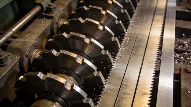
| Coil to slit strip | Knife setup, tension, burr control, recoiling, recipe repeatability | metal slitting line process guide |
| Coil to flat sheets | Leveling, length control, shear timing, stacking, surface protection | cut-to-length line definition and RFQ checklist |
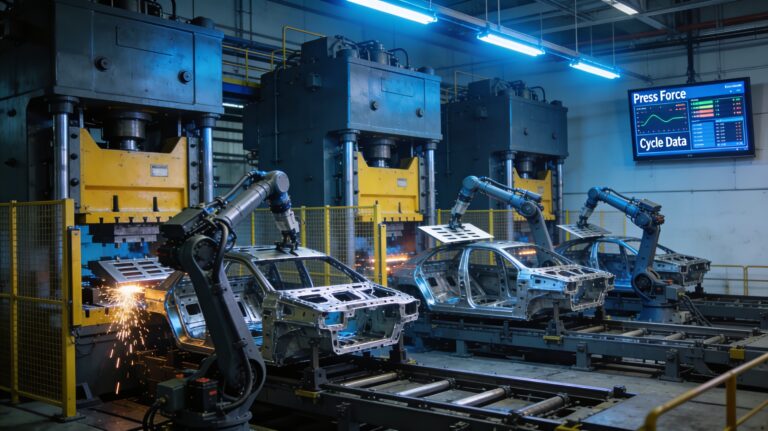
| Prepared strip to press | Loop control, feed pitch, press signals, die timing, misfeed protection | stamping press coil feeding integration checklist |
| Mixed coil service center | Model selection, changeover, product mix, operator workflow, reporting | MA and MD slitting model fit matrix |
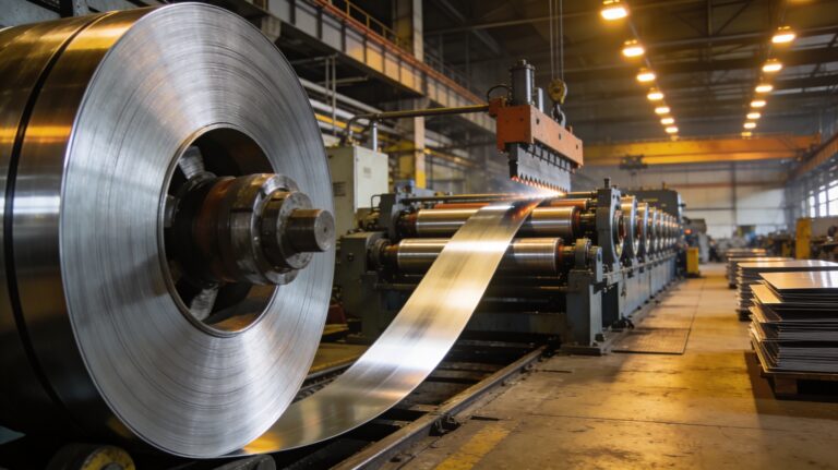
Separate System Layers Before Buying Hardware
An automated metal-processing line has several layers. The mechanical layer handles decoiling, feeding, leveling, slitting, shearing, recoiling, and stacking. The control layer synchronizes motors, tension, knives, shear timing, safety, and recipes. The data layer records production counts, alarms, energy, quality checks, and maintenance signals. These layers should be specified together but evaluated separately.
If the current line already has good mechanics but weak controls, review the slitting line control system upgrade roadmap. If the project needs a new automation standard across several production lines, use the implementation plan rather than treating the purchase as a single-machine replacement.
Match Automation Depth to the Production Problem
Automation should solve a measurable bottleneck. A plant chasing width stability may need better slitting setup and tension control. A plant losing yield may need recipe discipline and scrap tracking. A plant with frequent changeovers may need HMI recipes, tooling setup records, and standardized acceptance checks. A plant with deformation issues may need to address material stress before adding more sensors.
| Problem signal | Likely automation scope | Related MaxDo guide |
|---|---|---|
| Scrap and yield loss | Knife setup, coil nesting, measurement feedback, operator checklist | slitting scrap process loss map |
| Strip deformation | Tension path, residual stress, recoiling control, material handling | slitting deformation control checklist |
| Model uncertainty | Coil width, thickness, material, output format, growth plan | MD-1650 vs MD-2200 wide-coil boundary checklist |
| Supplier comparison | Acceptance criteria, delivery support, commissioning evidence | automated line manufacturer buyer scorecard |
Connect the System Map to Product Categories
Once the route and automation depth are clear, compare equipment categories instead of jumping to a model name. For slit-strip production, start with the metal slitting machine category. For flat-sheet output, start with the metal cut-to-length line category. If both routes are possible, compare slitting vs CTL line production fit before writing the RFQ.
Model-level selection should follow the route. Compact or thin-gauge projects can begin with MA-850 and the 850-class slitting setup-fit checklist. Mid-width slitting projects can compare MA-1350. Wider and heavier coil projects should evaluate MD-1650 and MD-2200 against material, width, thickness, speed, and future product mix.
Build an Automation RFQ From System Inputs
- Material data: grade, thickness, width, strength, coating, surface sensitivity, coil weight, and output tolerance.
- Route: slitting, cut-to-length, press feeding, mixed service-center workflow, or phased retrofit.
- Automation depth: mechanical automation, recipe control, servo control, alarm logic, inspection data, energy data, or plant reporting.
- Acceptance: test material, dimensional tolerance, edge quality, flatness, throughput, changeover time, alarm response, and training evidence.
- Growth path: current product mix, future coil width or thickness, integration with other lines, and service expectations.
For material intake, use the MD series material compatibility checklist and the gauge thickness RFQ helper. To turn this system map into a project review, send MaxDo the route, material data, output format, tolerance targets, automation depth, and commissioning expectations through the contact form.