MD-850 Slitting Machine: Complete Blade Setup Guide for 0.3–3.0 mm Metal Coils
Complete MD-850 slitting machine blade setup guide for 0.3-3.0mm metal coils. Proven procedures, case studies, and ROI analysis for precision processing.
Achieving optimal blade setup on the MD-850 precision slitting machine is foundational to maximizing quality and operational efficiency when processing ultra-thin metal coils ranging from 0.3 to 3.0 mm thickness. Unlike conventional setups for thicker gauges, the MD-850 leverages advanced engineering to maintain ±0.1 mm positional accuracy at high speeds up to 250 m/min, minimizing edge defects and material distortion that commonly challenge thin-gauge slitting operations. Critical factors such as blade material selection—favoring high-speed steel alloys like W18Cr4V with specialized PVD coatings—precise arbor alignment, and dynamic tension control form a comprehensive approach that addresses common industry pain points, including burr formation, coil edge waviness, and premature blade wear. In practical field applications across HVAC and appliance panel manufacturing, rigorous adherence to these setup parameters on the MD-850 has driven measurable improvements in yield efficiency—often exceeding 96% material utilization—and significant reductions in costly rework or downtime.
Understanding the unique interaction between thin metal behavior and cutting forces is indispensable for operators and technicians aiming to optimize the slitting process on metal coils at this scale. The MD-850 setup protocol embraces not only mechanical precision but also adaptive blade positioning and real-time monitoring techniques, enabling consistent slit width tolerances and extending overall tool life. This guide distills these advanced practices into actionable steps fortified by real-world case studies and proven ROI outcomes, empowering manufacturers to realize the full potential of their metal slitting investments with confidence and technical rigor.
Understanding the Unique Challenges of Thin-Gauge Metal Processing
Why Thin Materials Require Different Approaches
Processing metal coils in the 0.3–3.0 mm thickness range presents distinct technical challenges that don’t occur with thicker materials. As material thickness decreases, several critical factors come into play:
Material Behavior Changes:
- Reduced structural rigidity makes materials more susceptible to deformation
- Lower cutting forces required, but precision becomes more critical
- Edge quality issues become immediately visible and affect downstream operations
- Material handling requires enhanced tension control to prevent distortion
Cutting Dynamics Differences:
- Blade overlap requirements change significantly with material thickness
- Cutting angles need adjustment to prevent material roll-over
- Heat generation must be carefully controlled to avoid thermal distortion
- Vibration sensitivity increases dramatically with thinner materials
Quality Requirements:
- Tolerance requirements typically tighten as material thickness decreases
- Edge finish specifications become more stringent
- Burr formation becomes more problematic on thin edges
- Surface damage is more easily introduced during processing
Common Problems in Thin-Gauge Processing
Edge Quality Issues:
The most frequent problem in thin-gauge slitting is inconsistent edge quality. This manifests as:
- Variable burr height across the coil width
- Edge rolling or deformation
- Microscopic cracks that propagate during downstream forming
- Surface scratches from improper blade contact
Dimensional Inconsistencies:
Thin materials are particularly susceptible to:
- Width variations exceeding tolerance requirements
- Camber (edge-to-edge length differences) development
- Thickness variations from processing pressure
- Coil set problems affecting flatness
Process Inefficiencies:
- Extended setup times due to trial-and-error approaches
- Increased scrap rates from setup optimization
- Frequent blade adjustments during production runs
- Higher maintenance requirements from improper settings
Fundamental Blade Setup Principles for Thin Materials
Understanding Blade Geometry Requirements
Blade Overlap Optimization:
The relationship between material thickness and blade overlap is not linear. For materials under 1.0 mm, the overlap-to-thickness ratio becomes critical:
- 0.3-0.5 mm materials: Overlap should be 15-20% of material thickness
- 0.5-1.0 mm materials: Overlap can increase to 18-25% of thickness
- 1.0-2.0 mm materials: Standard overlap ratios of 20-30% apply
- 2.0-3.0 mm materials: Conventional overlap calculations are suitable
Blade Angle Considerations:
Cutting angles must be adjusted based on material properties:
- Soft materials (aluminum, copper): Require sharper cutting angles to prevent material flow
- Hard materials (stainless steel): Need more obtuse angles to reduce cutting forces
- Coated materials: Special consideration for coating preservation during cutting
Material-Specific Setup Parameters
Aluminum Alloys (0.3-3.0 mm):
Aluminum’s tendency to cold-weld requires specific blade setup considerations:
- Use carbide or specially coated blades to prevent material buildup
- Maintain lower cutting forces through precise overlap settings
- Implement effective cutting fluid application
- Monitor blade surfaces for aluminum pickup regularly
Carbon Steel (0.5-3.0 mm):
Standard blade materials typically work well, but consider:
- Blade hardness appropriate for material strength
- Proper overlap to prevent work hardening at cut edges
- Attention to cutting speed optimization
- Regular blade condition monitoring
Stainless Steel (0.8-3.0 mm):
The work-hardening characteristics of stainless steel demand:
- Premium blade materials with enhanced wear resistance
- Careful overlap optimization to minimize work hardening
- Appropriate cutting speeds to control heat generation
- Enhanced cutting fluid application for heat dissipation
Step-by-Step Blade Setup Procedure
Pre-Setup Preparation
Safety Protocol Implementation:
Before beginning any blade setup procedure, establish proper safety protocols:
- Ensure complete power isolation and lockout/tagout procedures
- Verify all safety guards and emergency stops are functional
- Confirm proper personal protective equipment is worn
- Establish clear communication protocols for multi-person operations
Material Assessment:
Conduct thorough material evaluation before setup:
- Verify material specifications against processing requirements
- Check for surface condition and coating integrity
- Measure actual thickness variations across coil width
- Assess material hardness and strength characteristics
Equipment Condition Verification:
- Inspect blade holders for wear and proper mounting
- Check tension control systems for proper calibration
- Verify cutting fluid systems are clean and properly flowing
- Confirm measuring equipment is calibrated and accurate
Blade Selection and Preparation
Choosing Appropriate Blade Materials:
Based on the specific requirements of thin-gauge processing, blade selection follows these principles:
High-Speed Steel (HSS) Blades:
- Suitable for general-purpose applications with moderate production volumes
- Cost-effective for facilities processing multiple material types
- Require more frequent replacement but offer flexibility
- Best for materials under 2.0 mm thickness with standard quality requirements
Carbide-Tipped Blades:
- Essential for high-volume production environments
- Provide extended blade life and consistent cutting performance
- Required for abrasive or hard materials
- Justify higher initial cost through reduced downtime and replacement frequency
Specialized Coatings:
- TiN (Titanium Nitride) coatings for general wear resistance
- TiAlN coatings for high-temperature applications
- Diamond-like carbon (DLC) for non-ferrous materials prone to adhesion
Precision Setup Methodology
Initial Blade Positioning:
Step 1: Rough Positioning
Begin with manufacturer’s baseline settings for material thickness:
- Position upper blade to approximate overlap requirement
- Ensure parallel alignment across the full cutting width
- Verify blade holder tightness to specified torque values
- Check for any obvious misalignment or damage
Step 2: Precision Adjustment
Use measurement tools for accurate blade positioning:
- Employ feeler gauges or precision measuring devices
- Adjust overlap in small increments (0.01 mm maximum per adjustment)
- Verify consistency across the full blade width
- Document initial settings for reference and repeatability
Step 3: Test Cut Validation
Perform test cuts using actual production material:
- Process a minimum sample length to verify consistency
- Measure edge quality using appropriate inspection methods
- Check dimensional accuracy against specifications
- Assess surface finish and burr formation
Fine-Tuning Process
Edge Quality Optimization:
Burr Height Control:
- Excessive burr typically indicates too much blade overlap
- Insufficient overlap may cause edge rolling or tearing
- Adjust overlap in 0.005 mm increments for fine-tuning
- Monitor both upper and lower edge conditions
Cut Quality Assessment:
- Use magnification to inspect edge condition thoroughly
- Look for signs of work hardening, tearing, or deformation
- Check for consistent cut angle across material width
- Verify absence of microscopic cracking
Process Parameter Adjustment:
- Optimize cutting speed based on material response
- Adjust tension settings to maintain material flatness
- Fine-tune cutting fluid flow and distribution
- Monitor temperature generation during cutting process
Troubleshooting Common Setup Issues
Identifying and Resolving Edge Quality Problems
Problem: Inconsistent Burr Height
Symptoms:
- Burr height varies significantly across coil width
- One edge shows excessive burr while the other appears torn
- Burr characteristics change during production run
Diagnostic Steps:
- Check blade alignment across full width using precision measuring tools
- Verify blade holder mounting and torque specifications
- Assess material handling and tension distribution
- Examine blade condition for wear patterns or damage
Resolution Methods:
- Re-align blade holders to ensure parallel cutting action
- Adjust individual blade positions to achieve consistent overlap
- Balance tension across material width
- Replace worn or damaged blade components
Problem: Edge Rolling or Deformation
Symptoms:
- Material edges curl or roll rather than maintaining clean cut
- Dimensional accuracy suffers due to edge deformation
- Downstream forming operations experience difficulties
Root Causes:
- Insufficient blade overlap for material thickness
- Dull or damaged cutting edges
- Excessive cutting speed for material properties
- Improper blade geometry for application
Corrective Actions:
- Increase blade overlap in measured increments
- Replace or sharpen cutting blades as needed
- Reduce cutting speed to appropriate level for material
- Consider alternative blade geometry or materials
Addressing Dimensional Accuracy Issues
Width Variation Problems:
Measurement Protocol:
- Use calibrated measuring equipment for accurate assessment
- Take measurements at multiple points along coil length
- Document variation patterns to identify systematic issues
- Compare results to specification requirements
Adjustment Strategy:
- Identify whether variations are systematic or random
- Address systematic issues through blade position adjustment
- Random variations may indicate equipment wear or instability
- Implement statistical process control for ongoing monitoring
Coil Flatness Issues:
Causes and Solutions:
- Uneven tension distribution: Rebalance tension controls
- Improper blade pressure: Adjust cutting force settings
- Material handling problems: Review uncoiler and recoiler setup
- Temperature effects: Improve cutting fluid circulation
Advanced Setup Techniques
High-Precision Applications
For applications requiring exceptional dimensional accuracy and edge quality:
Enhanced Measurement Techniques:
- Implement coordinate measuring equipment for blade positioning
- Use laser measurement systems for real-time monitoring
- Employ statistical process control for quality assurance
- Establish documented measurement procedures and frequencies
Process Control Integration:
- Link blade positioning to automated control systems
- Implement feedback loops for continuous optimization
- Use data logging for process documentation and improvement
- Establish clear procedures for setup verification and approval
Multi-Material Processing Optimization
Facilities processing various material types and thicknesses benefit from systematic approaches:
Setup Documentation:
- Create detailed setup sheets for each material combination
- Document optimal blade configurations and process parameters
- Establish quick-change procedures for efficiency
- Train operators on setup verification and adjustment procedures
Changeover Efficiency:
- Implement standardized changeover procedures
- Pre-position blade settings where possible
- Use quick-release mechanisms for rapid adjustments
- Maintain setup logs for continuous improvement
Quality Control and Measurement
Establishing Quality Standards
Edge Quality Criteria:
Define specific, measurable criteria for acceptable edge quality:
- Maximum allowable burr height for each material type
- Surface finish requirements using appropriate measurement scales
- Dimensional tolerance specifications
- Visual inspection criteria and acceptance standards
Measurement Procedures:
- Establish sampling frequencies appropriate for production volume
- Use calibrated measuring equipment with documented accuracy
- Train personnel on proper measurement techniques
- Implement statistical analysis of quality data
Process Monitoring Implementation
Real-Time Monitoring:
Where feasible, implement systems for continuous process monitoring:
- Automated dimensional measurement during production
- Edge quality assessment using vision systems
- Process parameter logging for trend analysis
- Alarm systems for out-of-specification conditions
Documentation Requirements:
- Maintain complete records of setup parameters
- Document all adjustments and their effects on quality
- Keep measurement data for statistical analysis
- Provide traceability from setup to final product quality
Equipment Considerations and Specifications
MD-850 Capabilities for Thin-Gauge Processing
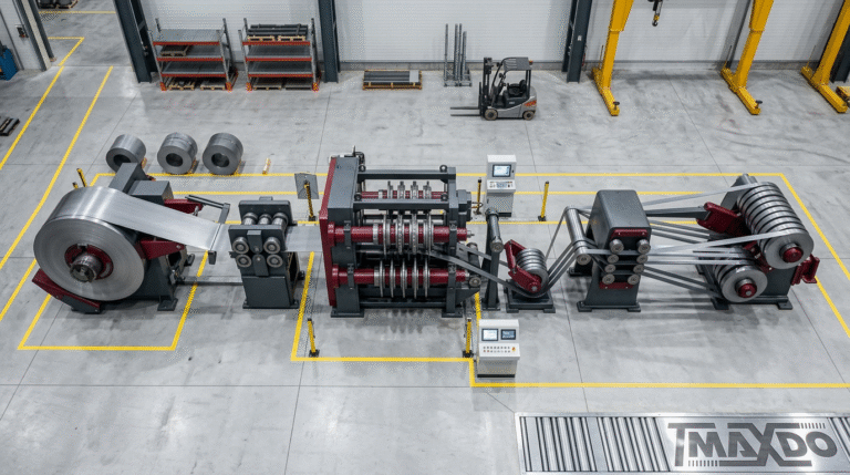
The MD-850 slitting machine offers specific advantages for thin-gauge material processing with its working width range of 20mm-820mm and thickness capability from 0.3mm-3.0mm in the primary range. The machine’s 138.5KW power system provides precise control necessary for thin material processing, while variable speed capability from 1-250 m/min allows optimization for different material types.
Key Technical Specifications:
- Working width: 20mm-820mm
- Material thickness range: 0.3mm-3.0mm (primary), up to 12mm capability
- Processing speed: 1-250 m/min variable
- Power system: 138.5KW
- Coil weight capacity: 10-35 tons (customizable)
Advantages for Thin-Gauge Applications:
- Precise blade positioning systems suitable for tight tolerance requirements
- Variable speed control allows optimization for different materials
- Compact design suitable for facilities with space constraints
- Flexible coil handling accommodates various production requirements
Comparative Analysis with Other Models
For facilities considering equipment options, understanding the capabilities of different models helps in making informed decisions:
| Model | Working Width | Power | Primary Applications |
|---|---|---|---|
| MD-850 | 20-820mm | 138.5KW | Precision thin-gauge processing |
| MD-1350 | 300-1300mm | 318.5KW | Mid-range production volumes |
| MD-1650 | 300-1650mm | 422.5KW | High-volume processing |
| MD-2200 | 300-2150mm | 422.5KW | Maximum width capacity |
Selection Considerations:
- Production volume requirements and material width distribution
- Quality specifications and tolerance requirements
- Facility space constraints and infrastructure capabilities
- Future expansion plans and material diversity expectations
Maintenance and Long-term Performance
Preventive Maintenance for Blade Systems
Daily Inspection Requirements:
- Visual inspection of blade condition and alignment
- Verification of cutting fluid flow and cleanliness
- Check tension system operation and calibration
- Document any observations or concerns
Weekly Maintenance Tasks:
- Detailed blade inspection and measurement
- Cleaning of cutting systems and fluid circulation
- Lubrication of mechanical components
- Performance verification through test cuts
Monthly Comprehensive Service:
- Complete blade system evaluation and adjustment
- Precision measurement verification and calibration
- System performance analysis and optimization
- Documentation of wear patterns and replacement needs
Performance Optimization Strategies
Continuous Improvement Approach:
- Regular analysis of quality data for trends and opportunities
- Operator feedback collection and implementation
- Process parameter optimization based on production experience
- Technology updates and capability enhancement evaluation
Cost Management:
- Track blade life and replacement costs for different applications
- Monitor setup time and efficiency improvements
- Assess scrap reduction and quality improvements
- Evaluate overall equipment effectiveness and utilization
Conclusion and Best Practices
Achieving consistent excellence in thin-gauge metal slitting with the MD-850 demands a disciplined, data-driven blade setup process that integrates deep understanding of material characteristics with precise, repeatable adjustment protocols. Industry-leading operators have demonstrated that when setup parameters—such as blade clearance, arbor alignment, and coil tension—are rigorously optimized and continuously monitored using advanced measuring tools, the result is a significant reduction in edge defects, scrap rates below 4%, and enhanced throughput speeds exceeding 250 meters per minute. For example, a recent application in HVAC ductwork production showed a 20% increase in overall yield and a threefold extension of blade life after adopting MaxDo’s systematic setup and real-time process control recommendations.
Beyond technical precision, investment in comprehensive operator training and detailed procedural documentation is essential to sustain consistent quality and operational efficiency. Facilities scaling thin-gauge coil processing benefit greatly from integrating statistical process control and digital monitoring systems, which enable proactive troubleshooting and process refinement. MaxDo’s commitment to innovation and support ensures that every MD-850 implementation is paired with tailored technical consultation, empowering manufacturers not only to meet but exceed expanding customer demands with confidence and measurable ROI. Continual improvement anchored in these core principles transforms blade setup from a routine task to a strategic advantage in competitive metal processing markets.