Slitting vs CTL ROI Decision Record
A narrow slitting vs CTL ROI decision record for documenting output geometry, order mix, tolerance risk, handling cost, setup loss, FAT/SAT evidence, and equipment routing.
This page is a narrow support page for slitting vs CTL ROI decision records in the MaxDo slitting and CTL topic network. It owns only the final investment decision record: output geometry, order mix, tolerance risk, handling cost, setup loss, material yield, FAT/SAT evidence, and equipment routing. It is not the main slitting vs CTL comparison matrix, not the material-risk routing checklist, and not the CTL process page.
A slitting vs CTL decision should be recorded as evidence, not argued from line speed alone. The right process depends on output geometry, order mix, tolerance risk, handling cost, setup loss, material yield, downstream bottlenecks, and whether the project can prove its assumptions during FAT, SAT, and commissioning.
This page is the ROI decision record in the MaxDo slitting and CTL topic network. For basic CTL definition, use what is a cut-to-length line. For material-specific routing, use the slitting vs CTL material risk checklist. This page focuses on how production and purchasing teams document the final investment decision.
Start the Record With Output Geometry
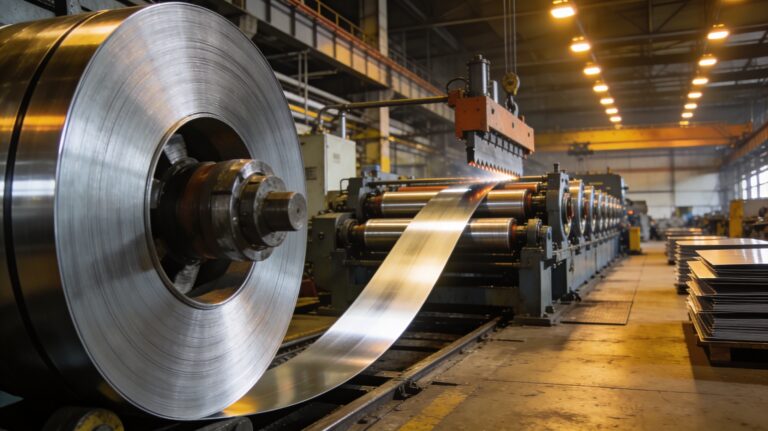
The first line of the decision record should name the required output form. Slitting is usually justified when the downstream process consumes narrow strip coil, such as roll forming, tube mills, or strip-fed stamping. CTL is usually justified when the downstream process needs flat sheets or blanks for fabrication, laser cutting, bending, panel work, resale, or press blanking. If the plant needs both outputs, record the split instead of forcing one process to carry both economics.
| Decision field | Slitting evidence | CTL evidence |
|---|---|---|
| Output form | Narrow coils or strips | Flat sheets or blanks |
| Downstream user | Tube mill, roll former, progressive press | Laser, fabrication, panel, resale, press blanking |
| Main tolerance | Width, burr, camber, coil build | Length, flatness, squareness, stack quality |
| Handling cost | Recoiling, separators, coil logistics | Stacking, pallet flow, sheet movement |
Record Order Mix Before Calculating ROI
ROI can be distorted when the model uses nameplate speed instead of real order families. Group historical jobs by material, thickness, width, output form, run length, changeover frequency, monthly tonnage, and downstream destination. Then calculate where the plant loses money today: purchased sheet premium, manual cutting, offcut, setup scrap, rejected strip, rejected sheet, queue time, rework, and extra handling.
For coil-to-output workflow context, connect the record to the sheet metal coil processing map. If the project is mainly a CTL and multi-blanking production cell, use the CTL and multi-blanking payback map before closing the ROI model.
Separate Tolerance Risk From Cost Savings
Some investments pay back because they reduce labor or scrap. Others are justified because they prevent quality risk. Keep those two reasons separate in the record. A slitting case should document width tolerance, burr, camber, edge quality, separator setup, and recoiling behavior. A CTL case should document length tolerance, flatness, squareness, surface condition, stack alignment, and sheet release quality.
For slitting measurement, use the slitting width tolerance measurement protocol. For CTL station evidence, use the cut-to-length process station acceptance map.
Convert Assumptions Into FAT and SAT Evidence
Every ROI assumption should have a proof method. If the model depends on less setup loss, define how setup time and setup scrap will be recorded. If it depends on fewer rejected sheets, define the inspection method. If it depends on faster changeover, define the job family and release gate. The record should show which assumptions will be tested at FAT, which at SAT, and which during the first month of production.
| ROI claim | Evidence to attach | Related checklist |
|---|---|---|
| Less setup loss | Changeover log, setup scrap, first-piece release | Setup time reduction |
| Better feed or cut accuracy | Sample set, measurement method, speed condition | Servo controller acceptance |
| Less material waste | Offcut, trim, reject, yield record | Slitting scrap loss map |
| Supplier claim validation | FAT/SAT form and deviation list | CTL supplier matrix |
Build the ROI Decision Record
- Output geometry: strip coil, narrow coil, flat sheet, blank, or mixed output.
- Order mix: material, thickness, width, run length, tonnage, changeover frequency, and downstream use.
- Quality risk: width, burr, camber, length, flatness, squareness, surface, stack, and recoiling behavior.
- Cost baseline: labor, purchased-sheet premium, offcut, setup scrap, rework, rejected product, and downtime.
- Proof plan: FAT, SAT, commissioning, first-month production record, and acceptance owner.
Route the Record to Equipment Paths
If the evidence points to strip output, compare the metal slitting machine category, including MA-850, MA-1350, MD-1650, and MD-2200. If the evidence points to sheet output, compare the metal cut to length line category, including Cutlength-850, CT-1350, and CT-1650.
For fabricator-led CTL decisions, review the cut-to-length lines for sheet metal fabricators value map. For thickness conversion before RFQ, use the gauge thickness chart. To ask MaxDo to review a slitting vs CTL ROI decision record, send the output form, order mix, cost baseline, quality risks, target proof plan, and preferred equipment route through the contact form.