Slit vs Blanked Defects: Diagnostic Protocol
A narrow diagnostic protocol for slit strip and blanked sheet defects, mapping symptoms to root causes, inspection checks, corrective actions, and product-route decisions.
Quality troubleshooting works best when production teams follow a diagnostic protocol instead of debating symptoms. Slit strip defects and blanked sheet defects look similar on a complaint form, but they usually come from different systems. A slit strip problem often points to knife setup, tension, strip path, or recoiling. A blanked sheet problem often points to leveling, feed accuracy, shear timing, flatness, or stacking.
For measurable pass/fail limits, start with the slitting vs blanking quality acceptance matrix. For equipment choice, use the core slitting vs blanking comparison page. This page is a narrow support page for slit-vs-blanked defect diagnosis. It owns only the diagnostic layer after a defect is found: product form, symptom family, likely root cause, first inspection check, corrective action, and product-route escalation. It is not the core slitting vs blanking comparison page and not the quality acceptance matrix.
Diagnostic Rule: Identify the Product Form First
Before inspecting the machine, identify whether the failed product is a continuous slit strip or a discrete blanked sheet. The product form tells you which systems can realistically cause the defect. This prevents a common mistake: adjusting the wrong part of the line because the symptom name sounds familiar.
| Failed product | Start diagnosis with | Systems to inspect first |
|---|---|---|
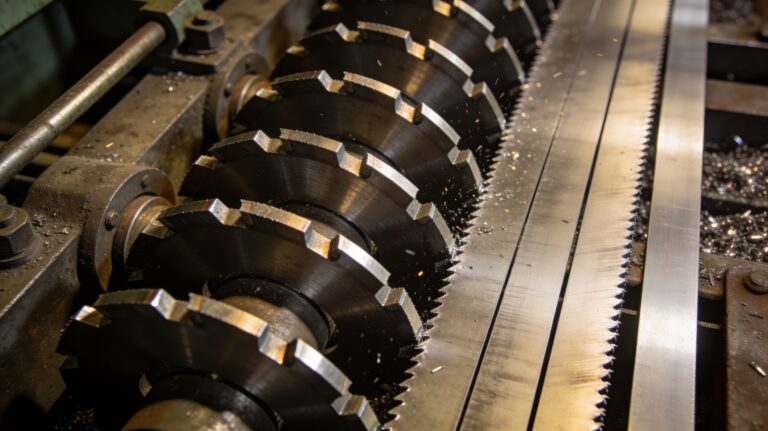
| Slit strip | Width, burr, camber, surface scoring, recoiling condition | Knife setup, tooling wear, tension zones, strip path, separator, recoiler |
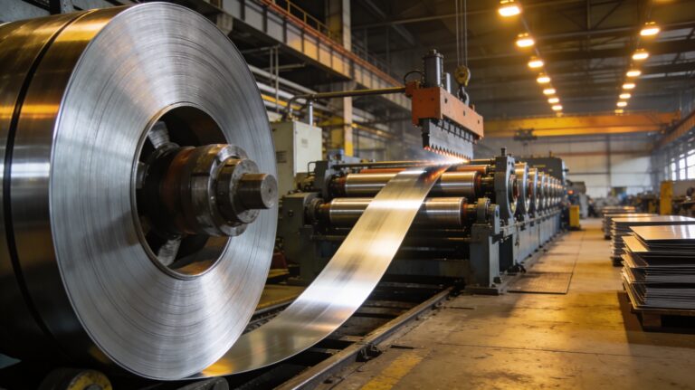
| Blanked / CTL sheet | Length, squareness, flatness, shear edge, stack quality | Leveler, servo feed, shear timing, conveyor, stacker, incoming coil condition |
Slit Strip Failure Tree
Use this sequence when the complaint is about slit strip output. Move from the visible defect to the machine system that can create it. Do not change multiple systems at the same time; otherwise the team cannot prove which correction worked.
| Symptom | Likely root causes | First checks | Corrective direction |
|---|---|---|---|
| Width drift | Knife spacing, arbor condition, tooling movement, tension instability | Measure strip width across start, middle, and end of coil | Verify knife setup, tooling lock, and tension consistency |
| Excessive burr | Knife wear, clearance error, material mismatch, poor alignment | Inspect burr side, knife edge, and clearance record | Reset clearance, replace worn knives, confirm material-specific setup |
| Camber or bow | Uneven tension, strip path error, material stress, recoiling pull | Compare camber before and after recoiling | Adjust tension zones and strip path; review recoiler behavior |
| Surface scoring | Contaminated rollers, separator contact, handling damage | Trace scratch location against machine contact points | Clean contact surfaces and adjust separator or handling path |
| Telescoped coil | Recoiler tension, separator setup, strip width mix, winding alignment | Check winding profile and tension history | Correct recoiler setting, separator position, and strip guidance |
For deformation-specific cases, use the guide on how to eliminate material deformation after slitting. For width-specific cases, use the guide on precision width tolerance in metal slitting machines.
Blanked Sheet Failure Tree
Use this sequence when the failed output is a flat sheet from blanking or a cut-to-length line. The main diagnostic difference is that the defect can come from incoming coil shape, leveling, feed measurement, shear timing, or stack handling after cutting.
| Symptom | Likely root causes | First checks | Corrective direction |
|---|---|---|---|
| Length error | Servo feed calibration, encoder error, slip, shear timing | Compare programmed length with measured first sheets | Verify feed calibration, encoder feedback, and shear synchronization |
| Flatness deviation | Leveler setting, incoming coil set, roller condition, material yield strength | Measure flatness before and after leveling | Adjust leveler penetration and confirm incoming coil condition |
| Out-of-square sheet | Feed alignment, shear alignment, material tracking | Measure diagonals and inspect feed path alignment | Correct feed guides, shear alignment, and tracking |
| Shear burr | Blade wear, clearance, shear timing, material mismatch | Inspect burr height and blade condition | Set blade clearance and review shear tooling maintenance |
| Poor stack quality | Conveyor speed, sheet release, stacker alignment, static or surface friction | Observe sheet transfer from shear to stack | Adjust conveyor, stacker guides, and handling timing |
Use the cut-to-length process guide to map these checks to decoiling, leveling, feeding, shearing, and stacking. For equipment paths, compare MaxDo metal cut-to-length lines.
First-Piece Diagnostic Protocol
The fastest way to isolate a defect is to separate first-piece approval from stable-running checks. First-piece problems often come from setup, calibration, and tooling. Stable-running problems often come from tension drift, thermal behavior, material variation, or handling after the line reaches speed.
- Record the material grade, thickness, coil width, target output, speed, and recipe or setup used.
- Measure the first acceptable piece and the first failed piece using the same method.
- Mark where the defect appears: before cutting, at cutting, after cutting, during recoiling, or during stacking.
- Change one variable at a time and record the result before changing another setting.
- Confirm the correction with repeated samples, not one good piece.
When the Root Cause Is Control Architecture
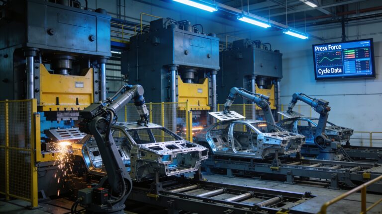
Some defects cannot be solved by operator technique alone. If the same problem repeats across shifts, materials, or setup teams, the root cause may be control architecture. Slitting defects may need better tension zones, servo positioning, recipe management, or process monitoring. Blanking defects may need feed control, leveler control, shear timing, or stack handling improvements.
For advanced slitting cases, connect the diagnosis to the advanced slitting control architecture matrix. For model fit, review the MA and MD model fit matrix and the MaxDo metal slitting machine category.
Corrective Action Matrix
| Defect family | Do first | Escalate if repeated |
|---|---|---|
| Slitting width or burr | Check knife setup, clearance, wear, and material-specific setup | Review tooling system, servo positioning, and operator setup procedure |
| Slitting deformation or camber | Check tension, strip path, separator, and recoiler settings | Review multi-zone tension control and material handling design |
| CTL length or squareness | Check feed calibration, encoder feedback, shear timing, and guides | Review servo feed control and shear synchronization |
| CTL flatness or stack | Check leveler setup, incoming coil condition, conveyor, and stacker | Review leveler capacity, stacker alignment, and material handling workflow |
If you need help diagnosing a repeating quality issue, share the material grade, thickness, coil width, defect photos, measurement records, speed, and where the defect appears in the line through the MaxDo contact form. A useful troubleshooting review starts with evidence, not assumptions.